How to design a proper USB-C™ power sink (hint, not the way Raspberry Pi 4 did it)
This issue came up recently for a high profile new gadget that has made the transition from Micro-USB to USB-C in its latest version, the Raspberry Pi 4. See the excellent blog post by Tyler (aka scorpia): https://www.scorpia.co.uk/2019/06/28/pi4-not-working-with-some-chargers-or-why-you-need-two-cc-resistors/
The short summary is that bad things (no charging) happens if the CC1 and CC2 pins are shorted together anywhere in a USB-C system that is not an audio accessory. When combined with more capable cables (handling SuperSpeed data, or 5A power) this configuration will cause compliant chargers to provide 0V instead of 5V to the Pi.
The Raspberry Pi folks made a very common USB-C hardware design mistake that I have personally encountered dozens of times in prototype hardware and in real gear that was sold to consumers.
What this unique about this case is that Raspberry Pi has posted schematics (thanks open hardware!) of their board that very clearly show the error.


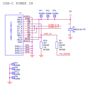
Both of the CC pins in the Pi4 schematic above are tied together on one end of resistor R79, which is a 5.1 kΩ pulldown.
Contrast that to what the USB Type-C Specification mandates must be done in this case.


Each CC gets its own distinct Rd (5.1 kΩ), and it is important that they are distinct.
The Raspberry Pi team made two critical mistakes here.
The first is that they designed this circuit themselves, perhaps trying to do something clever with current level detection, but failing to do it right. Instead of trying to come up with some clever circuit, hardware designers should simply copy the figure from the USB-C Spec exactly. The Figure 4–9 I posted above isn’t simply a rough guideline of one way of making a USB-C receptacle. It’s actually normative, meaning mandatory, required by the spec in order to call your system a compliant USB-C power sink. Just copy it.
The second mistake is that they didn’t actually test their Pi4 design with advanced cables. I get it, the USB-C cable situation is confusing and messy, and I’ve covered it in detail here that there are numerous different cables. However, cables with e-marker chips (the kind that would cause problems with Pi4’s mistake) are not that uncommon. Every single Apple MacBook since 2016 has shipped with a cable with an e-marker chip. The fact that no QA team inside of Raspberry Pi’s organization caught this bug indicates they only tested with one kind (the simplest) of USB-C cable.
Raspberry Pi, you can do better. I urge you to correct your design as soon as you can so you can be USB-C compliant.
