


-- Divider Test(Divider_test.vhd)
library IEEE;
use IEEE.std_logic_1164.all;
use ieee.std_logic_unsigned.all;
use ieee.std_logic_arith.all;
entity Divider_test is
port (
clk: IN std_logic;
ce: IN std_logic;
rfd: OUT std_logic;
dividend: IN std_logic_VECTOR(22 downto 0);
quotient: OUT std_logic_VECTOR(22 downto 0);
fractional: OUT std_logic_VECTOR(14 downto 0)
);
end Divider_test;
architecture RTL of Divider_test is
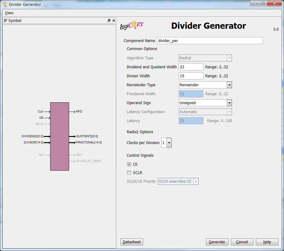
component divider_per
port (
clk: IN std_logic;
ce: IN std_logic;
rfd: OUT std_logic;
dividend: IN std_logic_VECTOR(22 downto 0);
divisor: IN std_logic_VECTOR(14 downto 0);
quotient: OUT std_logic_VECTOR(22 downto 0);
fractional: OUT std_logic_VECTOR(14 downto 0));
end component;
signal divisor: std_logic_VECTOR(14 downto 0);
begin
divider_per_inst : divider_per port map (
clk => clk,
ce => ce,
rfd => rfd,
dividend => dividend,
divisor => divisor,
quotient => quotient,
fractional => fractional
);
divisor <= "110000000000000";
end RTL;
LIBRARY ieee;
USE ieee.std_logic_1164.ALL;
ENTITY Divider_test_tb IS
END Divider_test_tb;
ARCHITECTURE behavior OF Divider_test_tb IS
-- Component Declaration for the Unit Under Test (UUT)
COMPONENT Divider_test
PORT(
clk : IN std_logic;
ce : IN std_logic;
rfd : OUT std_logic;
dividend : IN std_logic_vector(22 downto 0);
quotient : OUT std_logic_vector(22 downto 0);
fractional : OUT std_logic_vector(14 downto 0)
);
END COMPONENT;
--Inputs
signal clk : std_logic := '0';
signal ce : std_logic := '0';
signal dividend : std_logic_vector(22 downto 0) := (others => '0');
--Outputs
signal rfd : std_logic;
signal quotient : std_logic_vector(22 downto 0);
signal fractional : std_logic_vector(14 downto 0);
-- Clock period definitions
constant clk_period : time := 40 ns;
BEGIN
-- Instantiate the Unit Under Test (UUT)
uut: Divider_test PORT MAP (
clk => clk,
ce => ce,
rfd => rfd,
dividend => dividend,
quotient => quotient,
fractional => fractional
);
-- Clock process definitions
clk_process :process
begin
clk <= '0';
wait for clk_period/2;
clk <= '1';
wait for clk_period/2;
end process;
-- Stimulus process
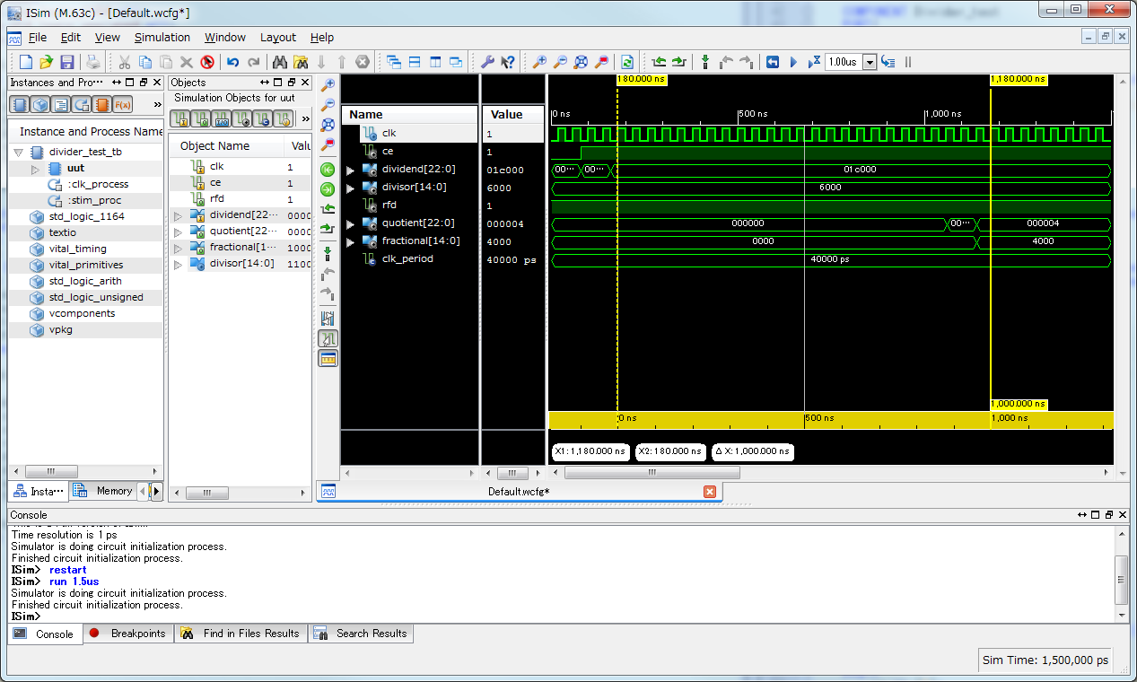
stim_proc: process
begin
ce <= '0';
dividend <= "00000000000000000000000";
wait for clk_period*2;
ce <= '1';
dividend <= "00000000110000000000000";
wait for clk_period*2;
ce <= '1';
dividend <= "00000011100000000000000";
wait for clk_period*10;
wait;
end process;
END;


| 日 | 月 | 火 | 水 | 木 | 金 | 土 |
|---|---|---|---|---|---|---|
| - | - | 1 | 2 | 3 | 4 | 5 |
| 6 | 7 | 8 | 9 | 10 | 11 | 12 |
| 13 | 14 | 15 | 16 | 17 | 18 | 19 |
| 20 | 21 | 22 | 23 | 24 | 25 | 26 |
| 27 | 28 | 29 | 30 | 31 | - | - |
© FPGAの部屋. Powered By fc2. Designed by WEBブログデザイナー

