GAMBOL

With critical contributions by Mike Ennamorato, Including this (edited) introduction.
Although nowadays the T-80 isn't nearly as famous as the T-72 and the T-90, it was understandably the most highly regarded item in the entirety of the vast Soviet tank fleet, and though they had T-72s stretching as far as the eye could see, it was the T-80s and the T-64s that formed the vanguard of the Soviet tank armies of the Rhine. However, it wasn't planned out this way in the beginning.
As one should come to expect from anything on the other side of the Iron Curtain, the T-80 has a rather intriguing story of inception. While the designers were still ironing out issues on the 5TDF opposed-piston engine for the T-64, experiments on mounting a turboshaft engine were already in full swing. It was requested that production expand from just Kharkov (KMDB) to Kirov (LKZ) and Nizhny Tagil (UKBTM) as well. Both of the latter plants struggled to produce some of the more complex parts for the T-64 - namely the engine - due to a lack of personnel familiar with the intricacies of the fundamentally different engines, and hence, created their own variations of the basic T-64. UKBTM (today a part of UralVagonZavod) and LKZ split design elements and ended off designing what came to be known as the T-72 and T-80 respectively. LKZ's progeny were defined by their signature turbine engines and more robust suspension, hybridized with the turret of the T-64A, thus forming the original model T-80.
This new vehicle was more extravagant and expensive than the ones preceding it, making the
T-80 much less common than the T-64 and T-72. It also came off as being a more ambitious project than UKBTM's T-72 (evidenced by a far longer development span). The T-80 came too late for its' own good. The instant it entered low-rate production in 1976, it was already surpassed in capability by both the T-64B and T-72A: a troubling situation for a vehicle meant to replace and supplement them, made worse by its excessive price tag. As a result, the T-80B was quickly ushered into service a mere two years after the T-80, boasting the ability to fire ATGMs from the cannon while on the move with the Kobra system, and an updated armour layout that had better prospects against the latest and future anti-tank munitions, and beginning from 1980, a more powerful 1100 hp GTD-1000TF engine. These upgrades along with the addition of Kontakt-1 explosive reactive armour - and a further enhanced armour package, formed the basis of the T-80BV, which arrived in 1985. The most advanced direct T-80 variant - the T-80U, also arrived in 1985, and came with a revolutionary - though flawed - heavy reactive armour package. This new model presented improvements to just about everything; a new digital fire control system, engine, explosive reactive armour, and some other tidbits.
So without any further ado, let's dive deep into the intricacies of the T-80!
Be sure to click on the photos if some of the details are too small. Most of the photos are not shown by their actual size
COMMANDER'S STATION

The commander is seated on the right hand side of the turret, entering via a rather tight armoured half-moon hatch. The hatch swings forward under spring tension, giving the commander a little leeway when opening it while the hatch itself offers protection from bullets when open. If the commander wants to fight outside the hatch or just take in the big picture with his head out and a pair of binoculars, he is almost fully shielded from sniper fire, and the hatch can be spun around along with the cupola to face any direction, so that's good too.
Just like with the T-64 before it, accommodations for the commander are spartan. His seat is well padded, and legroom is not in short supply, but there aren't many concessions for width. In summertime, the roominess of the station is acceptable for the average Soviet tankist, but in winter, the commander's bulky clothing cuts down on the already modest volume of habitable space. Taller people will not find it too bad, as there's plenty of headroom, though there's not much space to stretch out. Personally, I like to compare the turret stations with the cockpit of a fighter jet. The "pilot" sits in a narrow cabin with instruments to his left, right and center, and he talks to his "wingmen" via a headset and throat mike. He even traipses around with a jet engine whirring in the background.
For ventilation, there is a small plastic fan mounted on a ball joint just in front of him. It is enough for European summers, but not the high heat of Northern Africa and the Middle East.
Like with the T-72 and T-64, the commander of the T-80 is supplied with four general vision periscopes, but they got rid of the rearwards blind spot with the inclusion of a TPNT-1 rear view prism block embedded into the center of the hatch. It is useful for directing the driver while buttoned up. In non-combat situations, the commander could just open his hatch and peek out, of course. The TKN primary periscope directly in front of the commander is supplemented by two TNPO-160 periscopes and another two TNPO-165 periscopes embedded into the hatch, pointing left and right, thus giving him a very generous 180 degrees of frontal coverage around the turret, plus a "rear view mirror". While not as comprehensive as NATO tanks, the cupola is rotatable, so you still get 360° coverage in the end. Whether 360° vision is actually needed is an entirely different matter, as is the value of general vision periscopes. They are certainly useful for directing the driver, checking where your platoon mates are and getting a sense of direction and location, spotting well camouflaged vehicles and infantry from distances of several hundred meters and identifying them as such is simply not humanly possible while the tank is in motion.
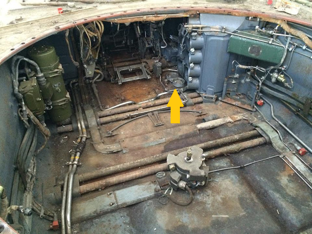
However, the commander's responsibilities are not limited to simply monitoring the situation outside. In case the autoloader malfunctions (which is so rare that none of the tankers that the author has talked to have ever encountered it), the commander is also responsible for manually operating the autoloader carousel. The ammunition type indexer memory unit (YELLOW) performs the double function of an indicator unit with LEDs in it to show what type of ammunition is currently aligned with the elevator and ramming mechanism so that the commander knows when he has reached the desired ammo type -
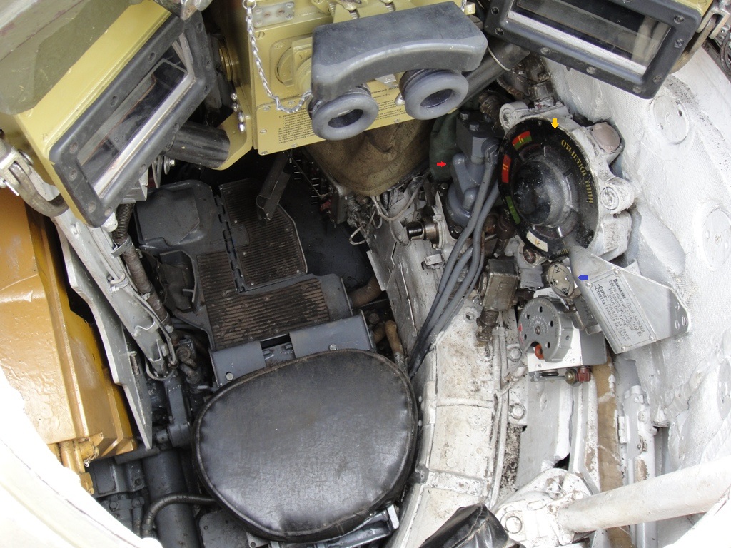
- and the silver-gray thing underneath it is the hydroelectric carousel rotation drive motor (RED). If all electrical power is cut to the tank, rotating the carousel is achieved by the commander furiously working the hand crank attached to the side of the motor.

The commander is also provided with an ammunition type selection dial (BLUE), which allows him to select the type of ammunition that is to be loaded, thus giving him the ability to make an immediate decision on the most suitable type of shell to use upon the identification of a target. For instance, if the commander sees a tank, he will immediately designate the target for the gunner to conduct final laying, and while the turret is still spinning, the autoloading cycle can already be underway. Thanks to this feature, the reaction time (the time between seeing a target and opening fire on it) can be as low as about 6 seconds total.
Besides all that, being the tank's auxiliary loader, the commander is provided a control box (GREEN) to control the autoloader replenishing procedure.
COMMUNICATION
(DLC REQUIRED)
Ventilation for the whole crew is provided by a drum-shaped ventilator unit located at the rear starboard corner of the fighting compartment.
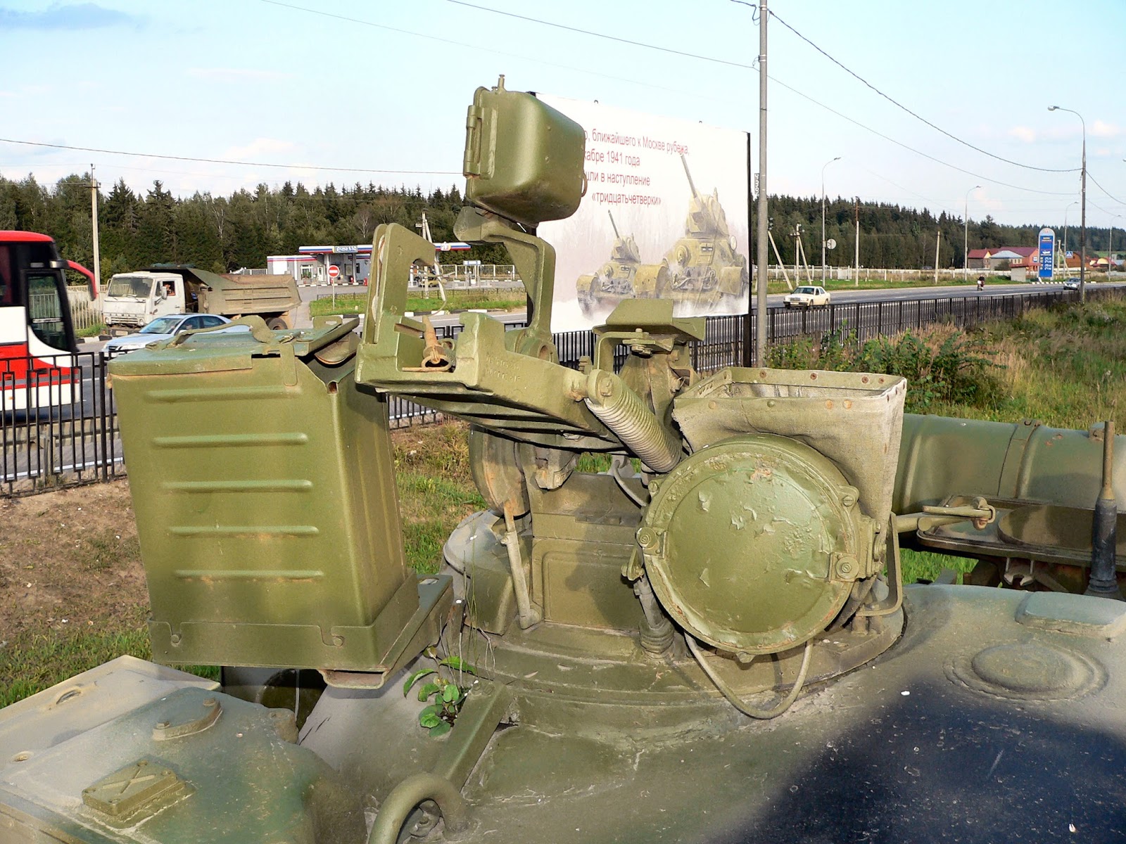
Besides having his general vision periscopes and controls, the commander also gets to play around with a multifunctional pseudo-binocular sight.
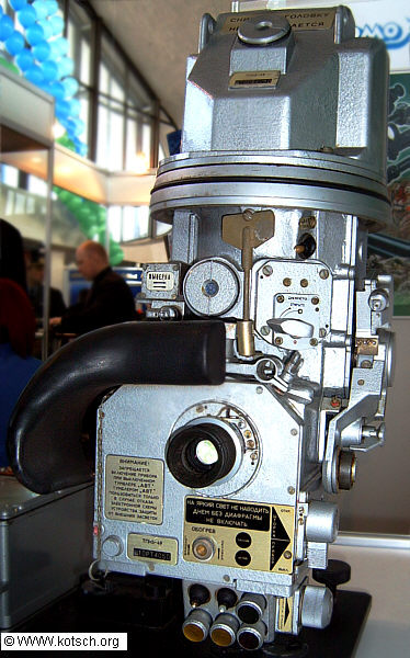
TKN-3 "Kristal"

By 1976, the TKN-3M was already somewhat obsolete. It featured target cuing and was very compact, but it wasn't stabilised, and featured only rudimentary rangefinding capabilities and its night vision capabilities were only borderline acceptable for 1976. Night vision came in two flavours; passive light intensification or active infrared. In the passive mode of operation, the TKN-3 intensifies ambient light to produce a more legible image. This mode is useful down to ambient lighting conditions of at least 0.005 lux, which would be equivalent to an overcast, moonless and starless night. In these conditions, the TKN-3M can be used to identify a tank-type target at a nominal maximum distance of 400 m due to the resolution limit, but as the amount of ambient light increases such as on starlit or moonlit nights, the distance at which a tank-sized target is discernible can be extended. In dark twilight hours, the TKN-3M may be able to make out the silhouette of a tank at a distance of up to 800 m or more, but the sight is hamstrung again, this time not by the absence of light, but by the low magnification. Any brighter than dawn or dusk, and the image will be oversaturated and unintelligible.
The active mode requires the use of the OU-3GA2 IR spotlight, which connects directly to the tank's 27V electrical system. With active infrared imaging, the commander can reliably spot vehicles from a distance of up to 2500 m to 3000 m, but identifying them can only be done at around 800 m, or potentially more if the opposing side is also using IR spotlights, in which case, the TKN-3 can be set to the active mode but without turning on the IR spotlight. The switch for activating the spotlight is the right thumb button while the operating channel selector is on the TKN-3 itself.
Though not as capable as the gunner's IR sight on the British Chieftain with its 1000-meter nominal identification range, it's worth noting that that system uses a 2 kW spotlight that has a diameter of around 570 mm. The OU-3GA2 consumes just 110 watts has an aperture diameter of only 215 mm, while still allowing the commander to see up to 80% as far as the gunner of a Chieftain can. The larger diameter illuminates a larger area, sure, but what the gunner can actually see is still limited by the field of vision of his sight, and there's nothing special there. It's also worth noting that the TKN-3 and the OU-3 series of spotlights was first introduced in 1964, three years before the Chieftain.
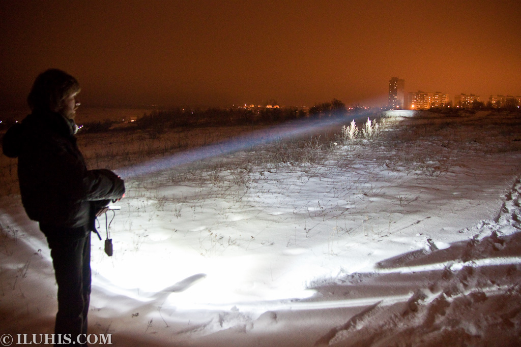
The problem with IR spotlights as a whole is that while the user can use them to spot for targets, the targets can use them to spot the user too, but from much further away. Because of the diffraction of light waves, you won't see just a circle patch of light either. If you observe a tank with its IR spotlight on, a large portion of the tank will be brightly illuminated from miles away. The diffracted light does have the benefit of lighting up the ground better for the driver to see, though, so the common issue of speed control due to short visibility distance with the complementary IR periscope for the driver is slightly alleviated in battle conditions.
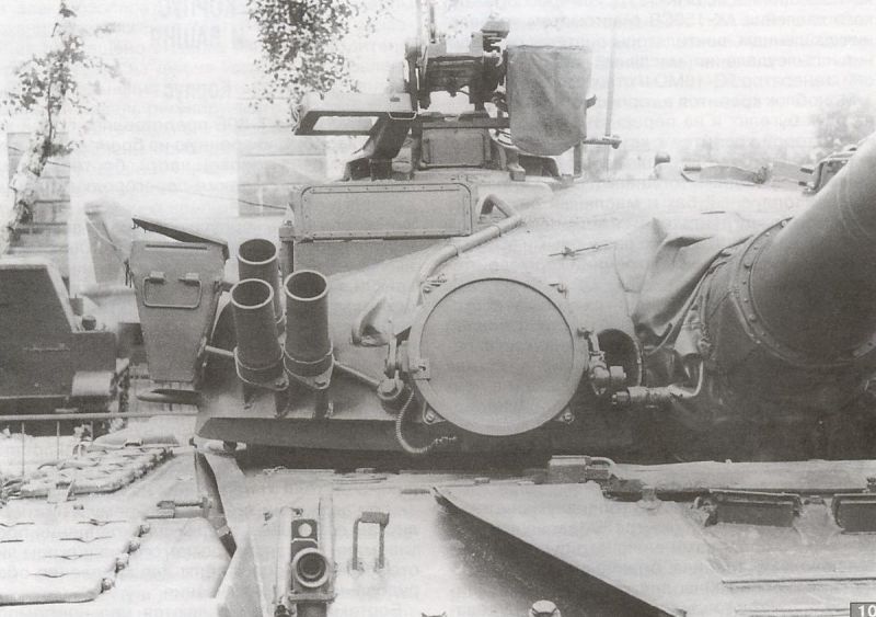
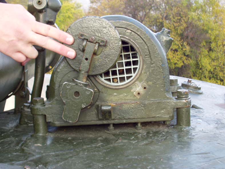
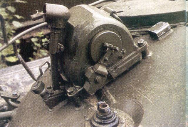
The OU-3GA2 spotlight is mounted co-axially to the TKN-3 sight aperture via a connecting rod, visible in the photo below to the left hand side of the spotlight.
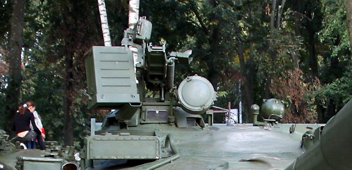
Rangefinding is accomplished through the use of a stadiametric scale sighted for a target with a height of 2.7 m, which is the average size of the average NATO tank. Like the TKN-2, the TKN-3 is unstabilized, making it exceedingly difficult to reliably identify enemy tanks or other vehicles at extended distances while the tank is travelling over rough terrain, let alone determine the range. The left thumb button initiated turret traverse for target cuing. The range of elevation is +10° to -5°. The OU-3GA2 spotlight is also directly mechanically linked to the periscope (the arm to which the spotlight is linked to can be seen in the photo above) to enable it to elevate with the TKN-3M.
Target cuing is done by placing the crosshair reticle in the periscope's viewfinder over the intended target and pressing the cue button. The system only accounts for the cupola's orientation, and not the periscope's elevation, so the cannon will not elevate to meet the target; only the turret will. This is not a very big problem, because the field of view of the gunner's sights was more than enough to guarantee that whatever was in front of him, he could see it more easily than the commander can.
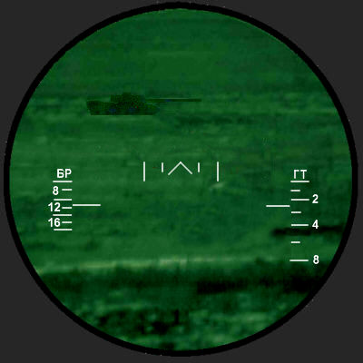
 |
| TKN-3 viewfinder |
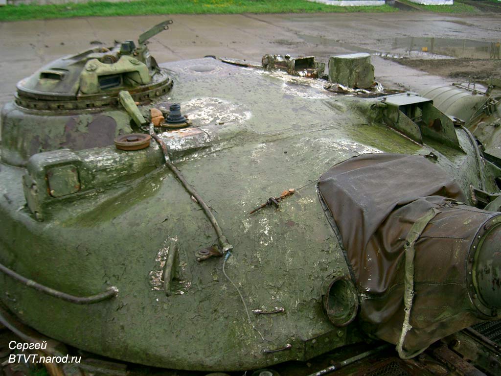
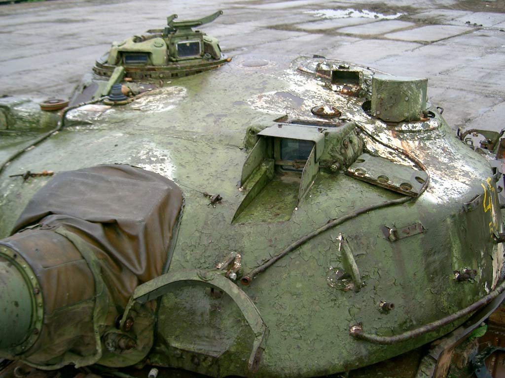
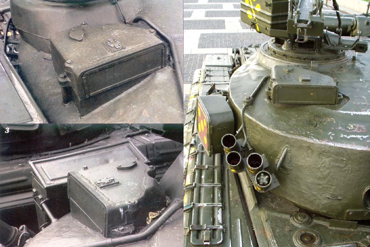
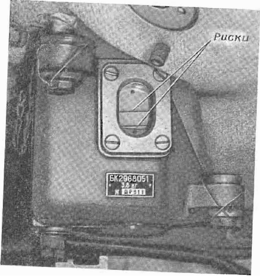
Although all the steel and equipment makes the cupola rather heavy, its ball bearing-ed race ring makes it surprisingly easy for the commander to rotate, enabling him to quickly and precisely slew his TKN-3M sight onto multiple targets, conduct ranging and designate them. Still, it isn't quite as easy to keep the sight on target once the turret starts spinning and the tank is moving away from the target at a large relative orientation angle, especially since the TKN-3M is always operating under maximum magnification. To remedy this, the cupola was equipped with an electric counter rotating (or "contra rotating", if you prefer) motor, visible in the photo below along with the electric cable supplying it with power. It is the box to the left of the dome light.

It is slaved to the turret traverse motor via a wire connection, causing it to rotate at a rate that is directly proportional to the speed of the turret, only in the opposite direction. This solves the problem of the commander losing track of the target, and it helps maintain his sense of direction.
PNK-4S Universal Sighting Complex


For the Soviet optronics industry at the time, the PNK-4S was only a small technical innovation, but it placed the T-80 on the same level as the best NATO tank, namely the Leopard 2 with its revolutionary PERI-R17 independent panoramic sight for the commander. Like the PERI, the PNK-4S complex combines the functionality of an auxiliary gunnery complex with that of a comprehensive surveillance unit, giving the commander full authority with regards to the fire control system, including the ability to directly override the gunner, which can be useful in some situations, such as to immediately engage a standout threat at the very instant it is spotted. All this is done with a simple thumbstick on the control module located to the right of the TKN-4S pseudo-binocular surveillance device around which the PNK-4S system revolves.

The decision to use a thumbstick was because a full joystick could not be easily manipulated with precision while the operator's body and arm was rocking around if the tank were going over rough terrain. However, the thumb would be completely stationary if the hand was securely gripping a handle. The index finger rests on the trigger.
The control module has all the necessary controls for the use of both the remotely controlled anti-aircraft machine gun on the cupola as well as the main gun, including ammunition selection vis-à-vis the autoloader. With this and the TKN-4S sighting complex, the T-80U could boast of having the most sophisticated hunter-killer regime in the world.
The foremost improvement of the TKN-4S over the TKN-3M is the addition of an independent stabilizer with its own gyroscopic sensor and compensator motor, visible on the left side of the main periscope housing as the large bulging module. The stabilization accuracy on the vertical plane is at least 0.30 mils, while the stabilization accuracy on the horizontal plane is much lower at 0.88 mils, because of the much greater burden of the cupola compared to the mirror in the sight aperture. This means that the maximum deviation from the original point of aim is 0.30 m vertically and 0.88 m horizontally at a distance of 1000 m. The sight can maintain this level of performance while the cupola is rotating at speeds of up to 35 degrees per second. The vertical range of elevation is quite reasonable, spanning from -10° to +20°, granting the commander an uninterrupted line of sight on any given target while the tank is on the move over terrain on any degree of impassibility (within reason).
The control module has all the necessary controls for the use of both the remotely controlled anti-aircraft machine gun on the cupola as well as the main gun, including ammunition selection vis-à-vis the autoloader. With this and the TKN-4S sighting complex, the T-80U could boast of having the most sophisticated hunter-killer regime in the world.
TKN-4S
The foremost improvement of the TKN-4S over the TKN-3M is the addition of an independent stabilizer with its own gyroscopic sensor and compensator motor, visible on the left side of the main periscope housing as the large bulging module. The stabilization accuracy on the vertical plane is at least 0.30 mils, while the stabilization accuracy on the horizontal plane is much lower at 0.88 mils, because of the much greater burden of the cupola compared to the mirror in the sight aperture. This means that the maximum deviation from the original point of aim is 0.30 m vertically and 0.88 m horizontally at a distance of 1000 m. The sight can maintain this level of performance while the cupola is rotating at speeds of up to 35 degrees per second. The vertical range of elevation is quite reasonable, spanning from -10° to +20°, granting the commander an uninterrupted line of sight on any given target while the tank is on the move over terrain on any degree of impassibility (within reason).
 Another major improvement came in the form of a much higher maximum magnification factor of x7.6 in the day channel, or x5.2 in the night channel. The field of view under x1 magnification is 47° for the day channel and 7° under maximum magnification, or 7°40' under maximum magnification in the night channel, owing to the much lower effective viewing distance at night, which is significantly improved over the TKN-3, but still not competitive performance against first-gen thermal imagers. The principal advantage of the increased magnification is that it enables the commander to see and designate targets at ranges suitable only for missiles and beyond what was determined to be the maximum effectiveness threshold for ballistic munitions.
Like the TKN-3, the TKN-4S can operate under active IR imaging or passive light intensification. In the latter case, under ambient lighting conditions no brighter than 0.003 lux, the TKN-4S facilitates the identification of a tank-type target at a distance of at least 700 m. The effective viewing distance increases as the lighting conditions improve, up until it is possible to engage larger vehicular targets like tanks and armoured personnel carriers at typical European combat ranges of about 1500 m on moonlit cloudless nights.
Because the TKN-4S is designed to use the same OU-3GA2 spotlight as the TKN-2, the active mode option does not present any improvements, only just enabling the commander to identify a tank-type target at a distance of 800 m. The difference is that this value does not change regardless of ambient lighting conditions. There is no possibility of increasing the viewing range in this mode using onboard means like the co-axial IR spotlight, effectively signalling that by 1985, active IR imaging would already be done for if not for the small upshot of being able to take full tactical advantage of mortar and artillery-delivered IR illumination flares, which can be aimed and shot over enemy positions. In such a scenario, however, the IR spotlight is rendered totally redundant, and because of this, the OU-3GA2 was deleted from the T-80 bloodline beginning in the T-80U. With hindsight, it is pretty clear that pursuing light intensification technology instead of investing in prospective thermal imaging technology was a huge mistake that ended up setting back the Soviet Union by nearly a decade in this particular field. Up until quite recently, modern day Russia had still been playing catch-up with Western tanks by assimilating French technology through technological cooperation.
However, that doesn't change the fact that while the TKN-4S had a fairly modern nightvision capability, the day-only PERI-R17 didn't, nor could it be used to control a remote large caliber machine gun, since the Leopard 2 didn't have one of those. So all in all, the TKN-4S was arguably the most advanced and most versatile commander's independent sighting complex available in the world, until that title was usurped post-Dissolution by the new CITV on the M1A2 Abrams in 1992 and the new PERI-R17A2 in 1998. Both had thermal imaging technology.
But besides all that, the TKN-4S has a neat x1 periscope installed just under the rubber forehead pad for wider forward vision, supplementing the two TNPO-160 periscopes flanking it. It's not much, but it does grant the commander an almost totally uninterrupted field of unmagnified vision around the cupola's front 180-degree arc.


Strangely enough, the PKN-4 complex does not include a laser rangefinder, despite the availability of quite compact designs already in the mid 70's. To determine the distance to a tank-type target, the commander must still rely on the same sort of stadiametric ranging scale as found on the TKN-3, though the precision of the operation has increased thanks to the higher magnification factor. Still, this isn't that big of a problem, because the gunner can quickly and painlessly conduct ranging himself anyway, and the gunner should be putting more time in observing the target than the commander anyway, who is supposed to be spending his time looking for other things to shoot at.
GUNNER'S STATION

The original T-80 turret was essentially identical in form and in function to the one from the T-64A, the T-80 itself being a derivative of it. Just like with the T-64A's turret, the gunner of the T-80 had nothing but a single front-facing periscope for general vision. Later on, both the T-80B and T-80U turrets placed two TNPO-165 general vision periscopes in and one TNPO-160 periscope aimed to the right, giving the gunner a good view of his surroundings when needed in addition to helping to improve the lighting condition of his station, which is pretty neat as well.


Keep in mind that in most NATO tanks, the gunner is not provided with any general vision devices at all, but inversely, the station is extremely cramped and amenities are few are far in between. Wider tankers will find it very difficult fitting into the station thanks to the massive GPS (Gunner's Primary Sight), but lankier people will find it decently accommodating, especially since the lack of a turret basket means that he will be able to stretch his legs. If the gunner is short and slim, all the better.

Besides the controls for gunnery related things, the gunner also has access to a multitude of toggle switches for a variety of things around his station. Among them are switches for the ventilation system (just below his hatch), switches for the dome light,
The new and more spacious turret of the T-80U also enabled the crew to carry a small number of additional cartridges. It certainly wasn't the most reassuring design feature, but most importantly, the ammunition somewhat reduced the available space, so removing them was quite normal.

Fire Control
Being the best tank in the Soviet Union meant a few things. One of them was having the best optics and compact computer technology money could buy.
One of the few interesting unique traits of Soviet-style sighting complexes was the control handles. Instead of a thumbstick like on the Chieftain or a pair "steering wheel" style hand grips where turret slewing was done by turning the handles like, well, a steering wheel (z-axis), spinning the turret was done by rotating the grips on the y-axis. The hand grips have two buttons each. The left trigger button is for firing the co-axial machine gun and the left thumb button is resetting the laser rangefinder. The right trigger button is for firing the main cannon, and the right thumb button is for firing off the laser rangefinder.
T-80 obr. 1976
TPD-2-49
The earliest T-80s were essentially modified T-64As, and as such, they had a great many things in common. Among these commonalities was the use of the TPD-2-49 optical coincidence rangefinder.

By 1976 standards, the TPD-2-49 was already incredibly outdated. It was first used on the original T-64 introduced in 1966, but since then, the TPD-K1 laser rangefinding sight had been invented and was already in use on the T-64B and T-72A, both introduced in 1976.
The optic aperture is split into two halves, top and bottom. The two input lenses see different parts of the same target, and the gunner must use the adjustment dial near his hand grips to line up both halves and obtain a seamless picture.
This process was cumbersome and somewhat inaccurate - the error margin was 3 to 5%, which meant that the range could be off by up to a shocking ±200m at 4000m, or a much less serious ±30m at 1000m range. However, it's worth considering that the average tank engagement distance expected in Europe was estimated to be 1500m, relieving the TPD-2-49 somewhat. Plus, the use of hypersonic APFSDS ammunition meant that the error margin could usually be ignored since the ballistic trajectory was so flat that amount of drop was completely negligible at out to 1500m or more. The problem was much more pronounced with HEAT and HE-Frag ammunition, which were heavier, had a worse ballistic coefficient and traveled at much lower velocities. With the advent of long range ATGM systems mounted on jeeps, scout cars, IFVs and even light tanks, accurate long-distance fire with HEAT and HE-Frag shells was imperative.
A major flaw with optical coincidence rangefinders in general is that they don't work very well on camouflaged targets. Tanks with some camouflage netting and some bushes stuck into them can be difficult to accurately range because the outlines of the tank may not be very clear to the gunner, and determining the silhouette through other visual cues is time consuming, not to mention that it requires at least a decently experienced gunner. And so, because the T-64A turret was practically obsolete the moment it was integrated as part of the T-80, only a few hundred of the original 1976 production variant were ever manufactured, which were subsequently brought back up to true 1976 technological standards with the retrofitting of the TPD-K1 sight.
TPN-1-49-23


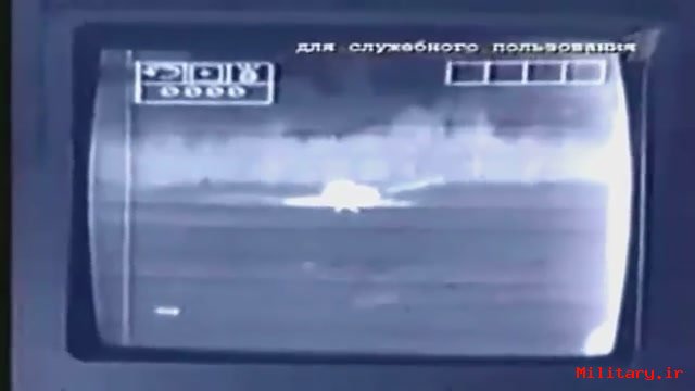
The TPN-1-49-23 is the gunner's auxiliary sight for the original T-80, but it was quickly replaced by the TPN-3-49. It can either use ambient light intensification or use infrared light conversion and intensification by relying on the L-4A "Luna-2" IR spotlight for illumination. The Luna-2 spotlight is mounted co-axially to the main gun. Like the commander's OU-3GA spotlight, the L-4A Luna spotlight is a xenon arc lamp with a simple IR filter. It runs on the tank's 27V electrical system and consumes 600 W of power. Removing the filter transforms the IR spotlight into a regular white light spotlight. Visual clarity can be cumulatively improved if multiple vehicles sporting IR spotlights, like BTRs, BRDMs, BMPs and other T-series tanks were illuminating the battlefield.
Take a look at this video here to see the L-4A spotlight in action.
The L-4A spotlight has an aperture diameter of 305 mm, smaller than the spotlights for the M60A1 and the Chieftain. The Chieftain's spotlight, for instance, has an aperture diameter of a staggering 570 mm, and consumes 2 kW of power. This is admittedly quite beneficial for searching for targets, because although the beam itself is only about 570 mm in diameter, dust, water vapor and smoke in the air help dissipate the light and increases ambient light levels, and illuminating a reflective object such as the ground will generate a bigger lit up spot. But despite the huge size and power of the spotlight, the nightsight on the Chieftain has an identification distance of just 1000 m. Despite using a much, much less powerful spotlight, the performance of the TPN-1-43-29 is quite close, with the ability to identify tank-type targets at around 800 m. The passive setting allows the same target to be spotted at ranges of up to 800m if the ambient light is no less than 0.005 lux, which is the typical brightness of a moonless, starlit night with clear skies. Clarity and spotting distance improves with increasing brightness. The identification distance is expanded to around 1000m on moonlit nights, and it is possible to spot tanks at distances of more than 1300m during dark twilight hours, although low magnification and mediocre resolution complicates viewing beyond that range. This level of performance is on par with the best Western equivalents of the mid to late 60's, but for 1976, the TPN-1-49-23 was simply no longer competitive. It did, however, have light intensification technology, which tanks like the M60 did not have until 1977.
If used as a backup sight, it can be used to identify tank-type targets at up to 3000m in daylight or more, if the geography and weather permits it. It has a field of view of 6 degrees at 5.5x maximum magnification. Variable zoom allows reduction of magnification to 1x to give the gunner much better general visibility for spotting targets.
The sight has dependent stabilization in the vertical plane with 20 degrees of elevation and 5 degrees of depression. Dependent stabilization means that the sight is technically stabilized, but it piggybacks on the vertical stabilizer for the cannon. Since the cannon has to elevate by +3 degrees for the loading cycle, the gunner will usually lose sight of his target immediately after firing, so he will be unable to observe the "splash" so that he knows how much elevation correction he needs to apply. The commander can see, of course, but that's not a very convenient way of doing things.
Though the cover can be removed and the sight used during daytime, the light intensification channel must never be activated, because excessive light input will overload the sight unit and possibly damage it. In accordance with this, the aperture has shutters linked to the trigger unit. Upon firing, the shutters automatically close to shield the unit from the intense flash of cannon fire at night. These shutter may also be manually opened and closed via a handle.
1A40 Sighting Complex
TPD-K1

The TPD-K1 is part of the 1A40 sighting complex, which included the TPD-K1 itself, plus the sight-stabilizer interface. It was first installed on the 1976 upgade of the T-72 Ural, which became the 'Ural-1', and later carrying over to the T-72A in 1979 and to the T-72B in 1983. It is the gunner's primary sight, mounted directly in front of him. It has a fixed 8x magnification and a 9° field of view.
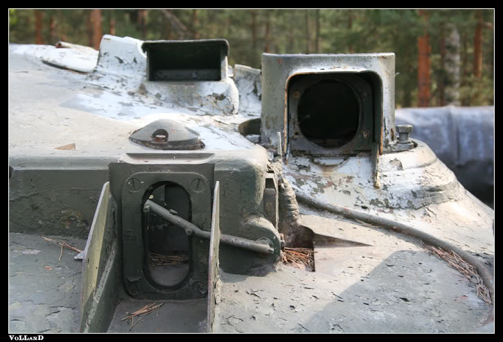
The sight aperture housing on the turret roof is armoured to withstand small arms fire, and a thin steel shroud extension shelters the aperture from thrown mud, rain, sand and snow; a rather clever feature, really. The extended side walls are of a much thicker steel meant to protect from bullets and fragmentation. The aperture itself has a layer of bolt-on SET-5L ballistic glass (19mm thick) to protect it from bullets and shell splinters. It is provided with a small wiper to remove any debris or mud that might obstruct the gunner's vision.
The sight aperture itself is just a periscope. There are no integral components in it, just a high-quality prism head with an interface with the stabilizer arms, so the financial loss from a destroyed sight head is totally negligible. Tank crews carry an extra sight head in internal stowage for quick field repairs.


The TPD-K1 replaces the TPD-2-49 and now that the secondary optic port is rendered redundant, it is permanently blocked off by having a plate welded over it. The primary optic housing was totally renovated to accept the much larger sight head of the TPD-K1.
The TPD-K1 incorporates a removable solid-state IR laser rangefinder (pictured below). It has a maximum error of 10m at distances of 500m to 3000m. From 3000m to 4000m, the maximum error threshold increases to 15m. The rangefinder becomes somewhat unresponsive and inaccurate past 3000m.
 |
| Detached rangefinder unit |
 |
| Attached to the right side of the TPD-K1 sight module |

It has a digital display for precise readouts, but range information is ported through to the range indicator dial on the top of the gunner's viewfinder, which the gunner can read for manual input if necessary. To lase a target, the gunner must place the illuminated red circle over it and fire off the laser for 1 to 3 seconds, less at closer ranges, adding about 1 second per every 1350 m. If the target is mobile, it must be tracked within the boundaries of the red circle until the range is obtained. The rangefinder unit must take 6 seconds to cool down between uses.
 |
| Range input unit |
Range information is automatically routed to the sighting unit, and the sight makes the necessary corrections and adjusts the reticle accordingly. The illustrations below shows what happens duing the ranging process.

Firstly, note the circle at the center of the viewfinder. That is where the target must go in order to determine the distance to it. Once that is done, the reticle instantly lowers, and the range indicator dial at the top spins to show the distance with an accuracy of within 10 m. The lasing circle stays where it is for lasing the next victim.
The 1A40 sighting complex features an accelerometer. Once the range data has been entered into the sight, the accelerometer begins measuring the distance traveled by the tank, also taking into account the direction of travel relative to the target that was lased. This means that the gunner only needs to lase a target once. The sight automatically calculates and registers the new range of the target even if the T-80 has driven several hundred meters since the last lasing. The accelerometer can be seen at work by observing the range indicator dial This allows the gunner to fire on the move without needing to repeat the entire target acquisition process all over again, which is quite time consuming. This form of directional compensation is sometimes regarded as the "third axis of stabilization".
 |
| Accelerometer. Smile! |
The TPD-K1 features a stadia-reticle rangefinder with distance indicators for ranges of 500m to 4000m that can be used to gauge target distance if the laser rangefinder is malfunctioning. This and the manual gun laying drives allow the gunner to continue engaging targets even if all aiming systems have completely lost power. The sight's vertical stabilization is linked to the vertical manual drive for cannon elevation.


The TPD-K1 is independently stabilized in the vertical plane. Thus, the gunner's view is not affected by any deficiencies in the gun's stabilization drives, and the gunner can see and engage targets beyond the gun's immediate capabilities in vertical elevation.

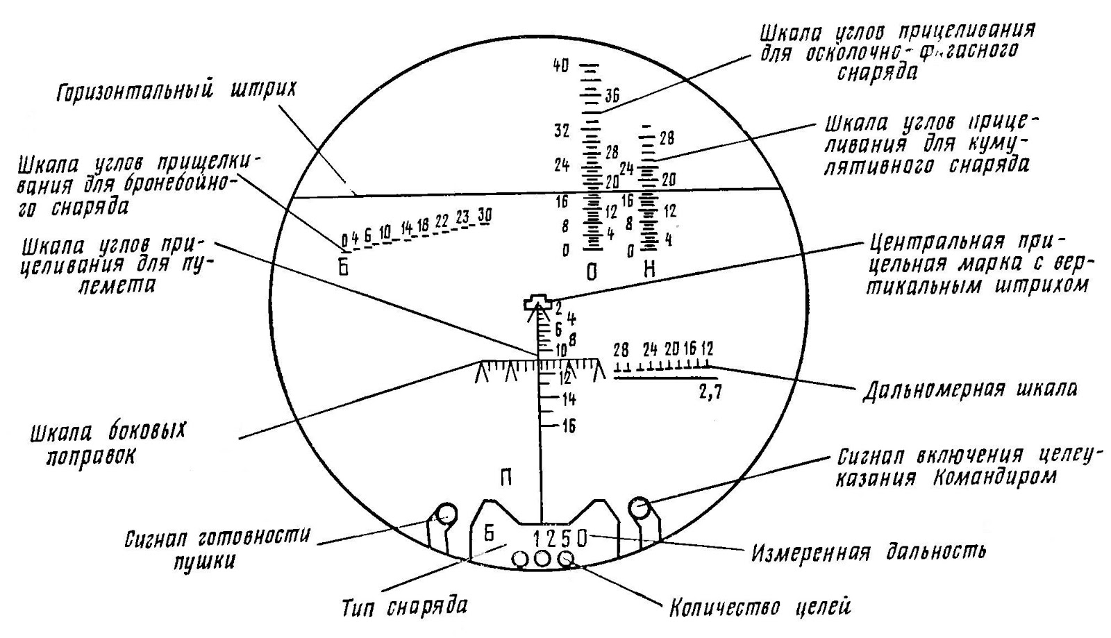
 |
| 1 - Ranging scales for co-axial machine gun (ПУЛ stands for Pulemyot, or machine gun), 2 - Ranging scales for HE-Frag shells (ОФ stands for High Explosive), 3 - Laser range finder distance indicator dial, 4 - Stadia-reticle range finder |
The sight includes graduations for firing the PKT machine gun to a maximum range of 1800m, for firing HE-Frag shells to a maximum range of 5000m, for manually applying lead on moving targets, and an auxiliary stadia rangefinder for manually determining the distance to a tank-type target or a bunker 2.7m in height at distances from a minimum of 500m up to 4000m (there is no need for a ballistic solution for targets closer than 500m). The stadia rangefinder is for emergency use only. On the top of the sight picture is the range indicator dial for the laser range finder, which is also capped at 4000m. Once the gunner has lased the target, the range will be displayed here. The gunner must then manually input the data into the analogue ballistic computer.
To operate the sight, the gunner must first toggle the type of shell into the sight's control unit beforehand.
Once this is done, the sight will automatically adjust itself for appropriate elevation. All the gunner must do now is to place the center chevron onto the target and fire. Subsequent shots do not require the process to be repeated, unless the gunner changes shell types or uses the co-axial machine gun, although already knowing the range, he may simply ignore the procedure and use the ranging scales to engage. Ammunition type selection is done with toggle switches right above the hand grips. One for HEAT-MP shells, one for APFSDS and another for HE-Frag.
 |
| Notice the blank spaces on the indicator card; these are left in anticipation of new ammunition. The introduction and use of 3BK-29, for example, would necessitate reprogramming the UVP unit at a depot. The card would then be filled in. |
But to fire different variants from the ammunition of each respective type, the gunner must first input the shell model into the UVP control unit (pictured above) in order for the sight to automatically obtain a firing solution. Once set, the sight automatically accounts for different ballistic characteristics of different projectiles. Of course, none of this is needed if operating completely manually.
TPN-3-49
Complementing the primary sighting complex from the original T-80 all the way to the T-80U is the obligatory nightvision sighting system, which also functions as the backup sight in the event of the destruction of the main sighting unit.

There are three selectable reticle settings for the viewfinder, one for each ammunition type; APFSDS, HEAT, and HEF. Each reticle different ranging scales for the gunner to input range data onto. Gunnery is reduced to its most basic level when using the TPN-3-49. Determining the range to the target is done by comparing the size of its profile with the size of the chevron, which is a rudimentary and rather imprecise method of rangefinding that is still implemented in the most modern sighting systems as a fallback option for when everything else fails. Unfortunately, this is the only way for the gunner to conduct rangefinding. However, it was determined that since the viewing distance was so short, it didn't really matter anyway.
The sight is not connected with the 1V517 ballistic computer, or any other third party sensor system. Laying the gun onto the target is done by lining up an adjustable horizontal line to an appropriate graduation on the range scale, which also moves the chevron up and down. So for instance, if a tank-type target is located 900 m away, the gunner places the horizontal line between the "8" mark and the long mark, which drops the chevron slightly. By using the handgrips to lay the dropped chevron up and back on target, the cannon is given proper supraelevation and a ballistic solution is formed.
The maximum identification distance of a tank-type target is 1300 meters in the active channel, and 850 meters in the passive channel under lighting conditions no brighter than 0.003 lux. As repeated many times before already, this figure will increase as ambient light gets brighter, but an important point to take is that the amount of ambient light needed to achieve the 850 m identification distance - 0.003 lux - is lower than the 0.005 lux standard by which the performance of the TKN-3 is measured by. This essentially means that on the same night, the gunner will be able to see about a half kilometer further than the commander.
In accordance with its function as a night sight, TPN-3-49 features an automatic internal shutter that blocks off the light intensifier device via an electric signal from the trigger on the TPD-2-49's handgrips. This is to protect it from burning out from the flash of the cannon firing, as the device is extremely sensitive and a bright flash of light so close to the sight will generate a sudden spike in voltage big enough to fry the vacuum tubes. Of course, the image produced would also be so bright that the gunner would go blind too. The light amplification channel must never be activated during daytime, because daylight is already bright enough to permanently damage the sight.
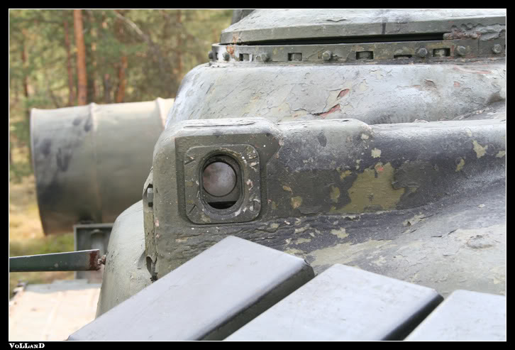
The armoured housing for the sight head of the TPN-3-49 can be distinguished by its small and squarish front profile, and the small bolt at each corner of the armoured cover. It is taller than the housing for the TPN-1-49-23.

T-80B (1978)
1A33 Sighting Complex
1G42

The T-80B was equipped with the more advanced 1G43 sighting system featuring the 1G42 primary sight. Like the TPD-K1, the 1G42 has an accelerometer and an independent gyroscopic relative position sensor enforcing an independent 2-axis stabilization system and also inputting distance and position corrections. Supplementing all that is the 1V517 ballistic computer, plus the 1B11 crosswind sensor and the 1B14 ambient temperature sensor.
GTN-12
The Kobra GLATGM is guided to its target via a radio command link, and the radio signal is transmitted by the GTN-12 antenna unit located directly in front of the commander's cupola. The transmitter is linked to the sighting system using the 9S416-1 control system, which translates movements from the hand grips and the shifting of the point of aim to generate a command signal for the missile, thus forming a SACLOS guidance regime.
The T-80A was also a patron to the Kobra system, but this was deleted in the later T-80U.
T-80U
1G46

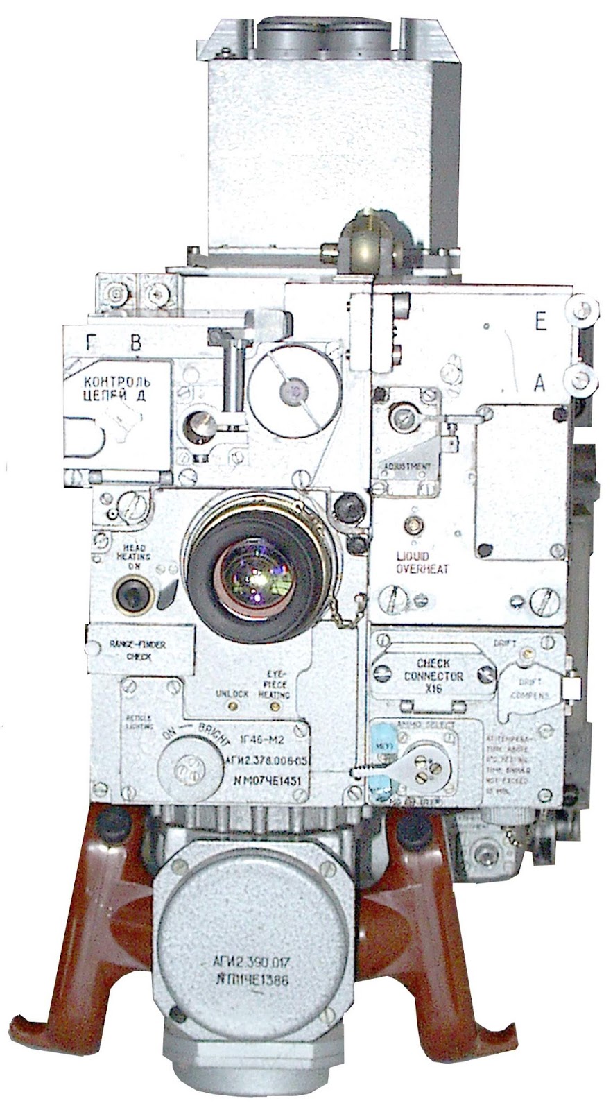
The independent stabilizer drives have an accuracy of 0.88 mrads, which equates to the ability to lay the chevron with a maximum error of 0.88 meters, which is incredibly bad given how simple it should be to stabilize a prism.
The 1G46 sighting complex also comes with a liquid cooled laser beam encoding and transmitting unit attached to it on the right hand side, not like with the T-72B, which incorporated its laser beamer for the "Svir" missiles in its auxiliary sight instead.

Other than the inclusion of the encoded laser projection unit, the 1G46 sighting complex is wholly unremarkable. Mediocre, even. The independent stabilization system for the sight head has an accuracy of mils, but most importantly, the sighting line drift is atrociously bad. If the tank is moving, the sight drifts away from the original point of aim at a rate of 0.2 mils per second, so in the space of five seconds, the chevron will have moved a full meter off target! This can be easily corrected by twitching the hand grips just slightly, but this does mean that the gunner has to be mindful.
http://ofbindia.gov.in/products/data/optical/add_38.htm
T01-P02-01 "Agava-2"


The revelation that new Western developments in thermal imaging technology was producing tank-borne sights that were rapidly outstripping the capabilities of light intensifiers resulted in new research on creating analogous devices to up the ante. Thermal imaging was not a totally unknown scientific field for the Soviet industry during the early 70's, as bare-bones prototype imaging systems for tanks had already been developed by the early 80'.
Working prototypes were already available by the early 80's, but problems with establishing mass production held up the development of thermal sights in the Soviet Union for a long time. In this sense, Soviet tank technology was behind the West by almost a decade, in both technological achievement as well as industrial know-how.
Only the command variant models of the T-80U, the T-80UK, had the Agava-2 installed due to their prohibitively high cost, which bloated the already incredibly high price of the T-80 tank series in general. But still, the Agava-2 had a few interesting quirks that are worth investigating.
Instead of an optical eyepiece or a "fishbowl" lens like the type found on the Abrams, the viewfinder on the Agava-2 was a 384x288p CRT monitor screen similar what the PZB-200 used. The sight itself is only capable of optical zooming on a limited basis, from 1.8x to 4.5x. To attain a greater degree of magnification, electronic interpolation (digital enhancement) is used to generate 18x zoom.
 |
| (Not actual resolution of viewfinder screen) |
While more than serviceable enough for combat distances in Europe,
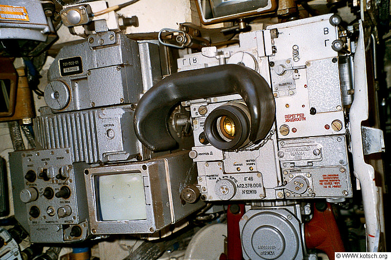
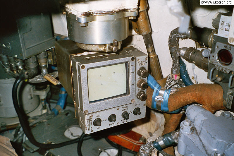
The commander is also provided with a 4.33" CRT monitor which feeds from the Agava-2, giving the commander a duplicate image of what the gunner is seeing.
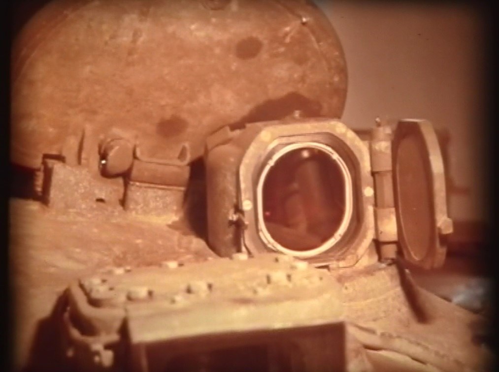
The armoured housing that protects the sight aperture can be distinguished from the one for the TPN-3-49 by a hinge on the left of the armoured window cover. The window can be opened from within the tank via a simple pullstring, as you can see below. This particular T-80 is an experimental T-80B equipped with the Agava-2. The armoured housing is identical between all models.

STABILIZERS
By 1976, it was practically unimaginable to not include full two-axis weapons stabilization as a prerequisite for any modern tank of the time.
2E28
The 2E28M 2-axis stabilizer is used in the original model T-80, being the newest stabilizer at the time of its development, while the 2E28M2 was used for the modernized T-80 with the TPD-K1. It is precise enough to guarantee hits on tank-sized targets at distances of up to a kilometer while travelling cross country at a speed of 30 km/h. The precision of the stabilizer is superior to the 2E28 "Sireneviy" used in the T-72 Ural, but inferior to the 2E42 "Zhasmin".
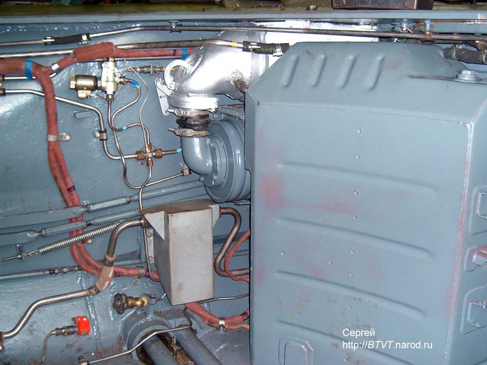
The hydroelectric generator for the hydraulic gun elevation mechanism is pictured below.
This stabilizer is incredibly slow to turn at only 18° per second. It would take it a minimum of 20 seconds to do a complete 360° revolution. This is a rather severe drawback, since it limits the gunner's ability to stay on target when the tank is executing high speed maneuvers, as the tank's ability to turn far outpaces the turret's ability to spin.
An inherent shortcoming of hydraulic stabilizers is their risk factor in case of turret penetration. Hydraulic fluid is highly flammable, and it would most likely cause and spread an internal fire very quickly. This is an especially serious concern to the T-80, since the layout of its autoloader does not shelter the ammunition from burning fluids.
2E38M2 uses MGE-10A, a type of mineral hydraulic oil with very low temperature sensitivity, having an operating range of between -65°C to 75°C. The entire system operates at 7.25 psi. This is quite dangerous, as with all hydraulic systems, because hydraulic oil may spurt out from burst tubes at high speeds, spraying large portions of the interior with the flammable liquid.
The entire stabilization complex is centered around the use of a gyrostabilizer meant for measuring angular velocities in order to enforce corrections. The weight of the sum of all the components is 320 kg.
Not many people care much about the maximum gun elevating speed attainable by the vertical drive of the gun stabilizer, which is understandable but rather naïve, because frankly, it can say a lot more about the quality of a stabilizer complex than actual gunlaying precision. As a tank travels over bumps and dips, it will oscillate on the vertical axis, meaning that the hull will pitch up and down relative to a level axis - the axis at which the gun needs to be on so as to point at the target. Vertical stabilization speed comes into play when factoring in the fact that the faster a tank travels over pockmarked ground, the faster it goes when it nosedives and tips up, and that means that the tank will be dipping and tipping faster relative to the aforementioned level axis in angular terms as well. In simple terms: the tank might drive downwards into a crater with a decline of 2° at a rate of -2° per second at 10 km/h, but it will drive downwards into the same 2° crater at a higher rate of -5° per second if it were going at 40 km/h, due to the higher speed, and so at that sort of speed, the cannon will not line up with the target. The 2E28M2 stabilization complex is able to guarantee that the gun stays exactly on target while the tank is travelling at 30 km/h over the average dirt road.
Vertical Stabilizer:
Maximum elevating speed: 3.5° per second
Minimum elevating speed: 0.05° per second
Horizontal Stabilizer:
Maximum turret slew speed: 18° per second
Minimum turret slew speed: 0.07° per second
2E26
Updated stabilizer system used in the T-80B.
The hydraulic fluid reservoir for both the 2E28 and 2E26 is mounted to the roof of the turret, just adjacent to the commander's head. It has a clear window with replenishing indicators. Maintaining the stabilizer and its associated subsystems is the gunner's responsibility.
2E42M1

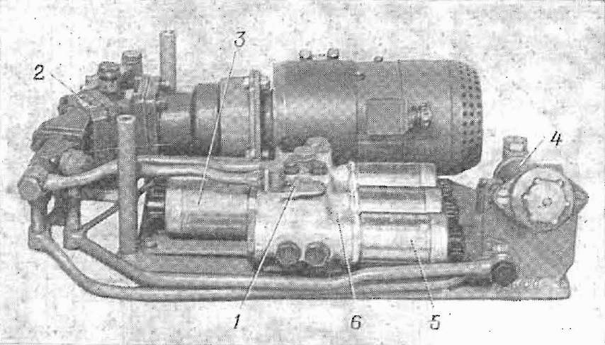
The components shown in the photo above are the amplidyne generator for the turret traverse motor, the hydraulic arm for the vertical stabilizer with its attached hydraulic pump, and the turret traverse motor itself, from left to right.
The photo below shows all of the components for the turret rotation mechanism. From left to right: Amplidyne generator, relay control box (to control rate of rotation), and the electric motor.

The 2E42M1 combines a hydroelectric turret rotation and stabilization drive with a hydroelectric cannon elevation and stabilization drive.
Thehydroelectric pump for powering the cannon elevation system is located under the cannon's breechblock, and the hydroelectric pump for turret traverse is installed in front of the gunner, behind his sight unit.
 |
| Amplidyne generator for 2E42M1 visible in the upper left corner of the photo |
The stabilizer is precise enough to lay the gun to within 0.05 mil on the vertical axis and 0.054 mil on the horizontal axis of the target at a distance of 1000 meters, meaning that the gun can be lain with an accuracy of at least 0.05 m on the vertical plane and 0.054 m on the horizontal one. Besides being more precise than the 2E28M-2, the horizontal stabilizer motor is also more powerful, giving the turret on the T-80U a much needed faster spin to accompany the tank's increased agility.
Vertical Stabilizer:
Maximum elevating speed: 3.5° per second
Minimum elevating speed: 0.05° per second
Horizontal Stabilizer:
Maximum turret slew speed: 24° per second
Minimum turret slew speed: 0.054° per second
The sum total of the components belonging to the stabilization system weighs 320 kg.
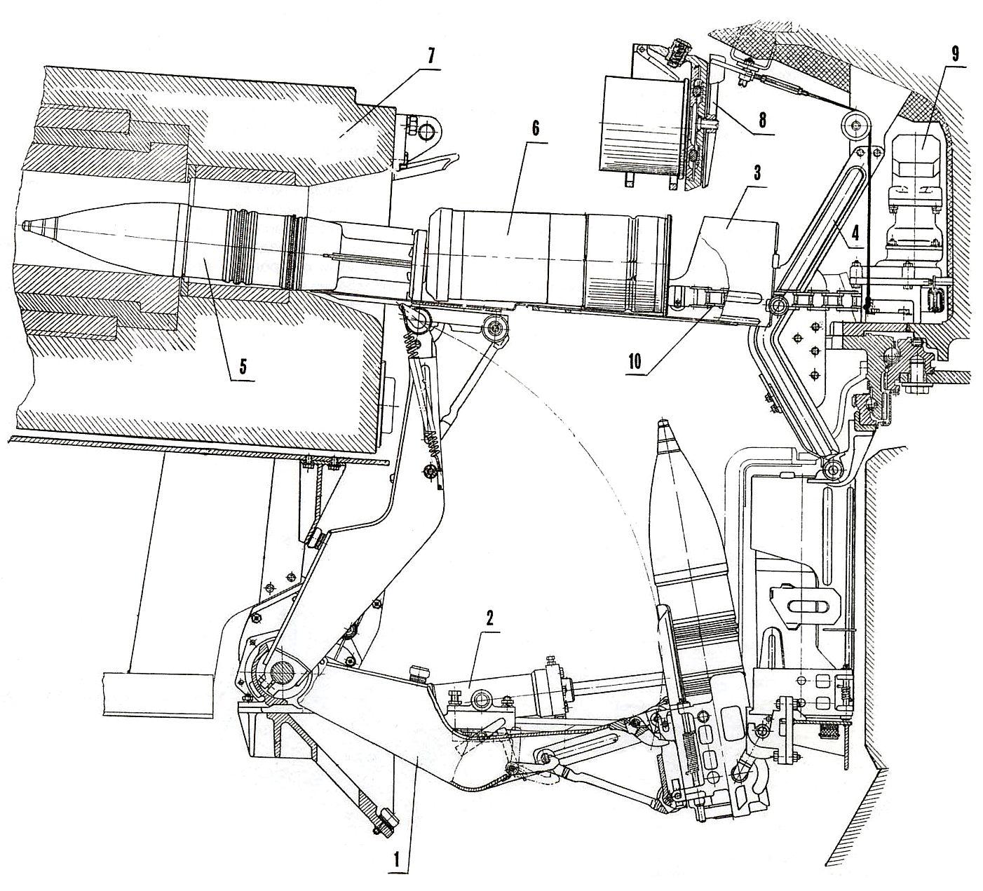
AUTOLOADER

Being a direct offshoot off of the T-64 family, the T-80 inherited its autoloader directly from its parent design. Designated the 6ETs-15 and officially nicknamed "Korzina" (meaning "basket), the autoloader is of a hydroelectric type. Between it and the AZ autoloader used on the T-72 series of tanks, it is quicker to load and has a considerably larger capacity, but it has its own peculiarities and drawbacks nevertheless.
The two-part cartridges are stowed in an 'L' position. The propellant charges are held vertically and the projectiles are held horizontally.

The biggest advantage to the 6ETs-15 autoloader is of course the fact that it holds a remarkable 28 rounds of ammo, more than the 22 rounds carried on the T-72, much more than the 16 rounds in the bustle of an Abrams, and nearly double that of the 15 rounds on the Leopard 2. The biggest, albeit minor drawback is of course the fact that while the human loader on a Leopard 2 or an Abrams are trained to load a shell in a minimum of four seconds, five if the opening of the bustle and the realigning of the cannon is added in, the "Korzina" autoloader can only manage to do so in five; six if the time needed for the carousel to rotate and the cannon to realign is included. However, the duration within which the respective loaders are able to maintain their rates of fire is a different matter entirely.
While certainly slower by about a second on average, the autoloader is insensitive to scorching heat, freezing cold, nor does it care how fast the turret is spinning, thanks to its impeccable sense of balance. It does not matter if the tank is rocking around like a bucking bronco at 50 km/h over the most gutted dirt paths. The autoloader will still load a shell in 6 seconds, every time. The argument that the autoloader can be "knocked out" by hard impact or a hit on the tank's armour is fallacious. A hit that's powerful enough to disable the autoloader would also be powerful enough to knock the people inside the turret out of their senses, and that includes human loaders. From an economics standpoint, an autoloader makes sense too. These really aren't complicated machines. Manufacturing one can take a few dozen cumulative man hours, but training a loader would take at least around 3 months, and a shoddily trained candidate will not be able to perform "up to spec". Of course, it can be pointed out that depending on unskilled labourers to assemble the autoloaders would also produce the same effect, but really, these aren't complicated machines.
But returning to the so-called "issue" of the 6-second loading speed, one must first take into account the amount of time that the gunner needs to be ready to fire. He must determine the range to the target first, and on the original T-80 with the TPD-2-49 optical coincidence sight, that can take a good four seconds.
The cartridge trays are composed of two hinged halves, both of which are skeletonized to save weight.

The second half of the tray is levered up from the rotary elevator acting upon an angled lug in front of its hinge point with the first half of the tray. The same elevator supplies most of the force propelling the tray upwards, and it also helps support the weight of the tray when it is unfurled.
The first half of the tray has an eccentric mounting point for the system of levers of the alignment mechanism to act upon. The eccentric installation is very apparent in the GIF above, which neatly demonstrates how the tray is cammed backwards into the rear bulge of the turret in order to create enough room for the second half of the tray to be pulled up before the entire assembly straightens out.

As you can see in the GIF above, the two halves of the tray split apart and release the cartridge from its bonds just a moment before the ramming cycle begins. When reloading the trays, these halves must be locked together before the tray can be indexed and lowered back into the autoloader.
Ramming is conducted by a rigid chain actuator.
Restocking the entire load of ammunition including non-autoloader stowage can take between 25 and 30 minutes to complete, while replenishing the ammunition reserves of the autoloader carousel takes between 15 and 20 minutes. Reloading the autoloader is a simple process. All that happens is that the normal loading cycle is reversed, so instead of shells being rammed into the breech of the cannon, the trays are raised into position, where they are loaded up, then lowered back into the autoloader.
One of the peculiarities of the "Korzina" autoloader is that the entire row of cartridges stowed around the perimeter of the turret ring completely isolates the driver from the rest of the crew. This makes it practically impossible for the commander to communicate with him without using the intercom system. However, the designers were kind enough to create provisions for creating a passage between the driver's station and the turret. This involves keeping the turret oriented exactly forward and removing any two ammunition trays which happen to be within the sector of the passage.

LOOSE STOWAGE
Whereupon the entire load of ammunition in the autoloader has been expended, the crew has the option of replenishing it with extra cartridges from racks placed here and there all around the interior of the fighting compartment of the tank. The original T-80 and the T-80B had a rather small reserve capacity of just 7 cartridges, stowed in the hull in a conformal fuel tank-cum-ammo rack located on the port side of the hull, just behind the driver's seat.

The new T-80U and its turret had space to store 10 extra cartridges. Stowing extra ammunition in the turret was a substantial security risk with the chance of catastrophic ammo detonation jumping up by two times, since now the turret and not just the hull was potential cause for a popped turret. So as mentioned before in the "Gunner's Station" segment, the crew could, and would have opted not to make use of the racks in the turret.
CANNON

There only ever were a few things in common between the members of the Soviet tank triad, and the cannon was one of them. Like its brothers, the T-80 mounted the 2A46 125mm smoothbore cannon, but along with the T-64, the T-80 was consistently ahead of the T-72 in implementing the latest and most advanced variants of the 2A46 family.
The initial T-80 employed the 2A46-1 cannon (D-81TM), a variant of the original 2A26 (D-81T). Both of these guns had previously been fitted to the T-64A upon which the T-80 shared many components, so this commonality comes as no surprise. Contrary to the older D-81T's length of 51 calibers (~6350mm), the D-81TM was shortened to 48 calibers (6000 mm) in barrel length - the superfluous length of 51 calibers had proven itself to be excessive for what Soviet barrel technology could support during that era. Correspondingly, there were issues with barrel lacking stiffness when in movement causing concerning accurate issues, among others. Fortunately for the T-80, it never had to deal with these problems. As it was just an evolution over the older cannons, the 2A46-1 shared almost all of there characteristics - the notable exceptions being a longer barrel life, of 800 EFC in place of 600.

AMMUNITION
PROPELLANT CHARGES

The GUV-7 electric/percussion primer is used, giving the option to either fire the shell normally using the fire controls on the gunner's hand grips or the button on the manual traverse flywheel, or to use the manual lever-operated striker pin incorporated into the gun's breechblock.

Zh 40

Original propellant charge designed for the 2A45 used in the first T-64. It uses 15/1TR VA propellant compound. Its most distinctive quality is the ghastly amount of fumes it produces upon firing.
Charge mass: 5.66 kg
Length: 408mm
Zh 52

Newer propellant charge modified to produce minimal smoke upon firing without changing its ballistic potential to maintain compatibility with all shell types excluding high-energy APFSDS ones. It uses 12/7 VA propellant compound. This model has completely replaced the Zh40 in frontline use. Here is a video of the Zh52 propellant charge being opened up: click

Charge mass: 5.786kg
Length: 408mm
Zh 63
High-energy propellant to launch APFSDS shells at even higher velocities. It uses 16/1TR VA propellant compound. It can only be used with newer APFSDS shells.
Charge mass: 5.8kg (?)
Length: 408mm
Fuses
V-15
Two part superquick, distance armed piezoelectric fuse. Point-detonating design that has provisions for graze initiation to allow detonation despite steep angles of incidence. It is distance-armed 2.5m from the muzzle.
V-429E
The V-429E fuse is point-detonating, distance armed and with variable sensitivity settings. It has two settings - superquick and delayed. The former is fixed at 0.027 seconds and the latter at 0.063 seconds. Superquick action guarantees reliable detonation in snowy or swampy ground, and delayed action gives a small time allowance for the shell to penetrate its target before detonating. This is meant for bunker busting and for erasing light vehicles from existence.
Contrary to some allegations, the fuse will not detonate by jolting or by touching the gun barrel's canvas muzzle when firing, or by touching rain drops for that matter. The fuse is distance-armed only after traveling 5m to 20m from the muzzle, precluding the possibility of accidental detonations, even without the protective cap and even in the superquick setting.
Ainet Timed Fuse
HE-Frag
The T-72 normally carries 12 HE-Frag shells in the autoloader, although this will almost certainly vary by situation. These shells have traditionally been predominant in Soviet armoured tactics, where tanks were regarded as the tip of the spear during breakthroughs. Bunkers, ATGM teams and troop concentrations - not tanks - were the bane of any and all armoured targets, and thus became high priority targets. Heavy breakthrough tanks with thick armour for charging down anti-tank guns to clear the way for calvary tanks were once the main counterforce, but with the advent of the Main Battle Tank and the phasing out of heavy tanks, the T-72 takes over this role in full, fulfilling both the role of a breakthrough heavy tank and calvary tank. HE-Frag shells therefore comprise the most important part of the T-72's loadout.When attacking infantry in the open, such as anti-tank teams, advancing troops, or machine gun nests, the fuze should be set in the "superquick" mode, giving it a delay of 0.027 seconds to ensure that the shell will detonate instantly upon meeting soft ground like mud and snow, allowing it to exploit its thick steel shell to its fullest as shrapnel.
When attacking reinforced concrete targets like bunkers and pill boxes, the shell could be set in the "penetrating" mode, giving it a delay of 0.063 seconds (as mentioned above), allowing the shell with its thick steel casing to travel a fair distance into target material before detonating, which is great because the impact of the big, heavy shell creates fractures, cracks and fault lines, making it a lot easier for the explosives to blow apart the entire structure. If targeting civilian buildings like houses, the shell would have no problem at all passing through cinder block or brick walls, allowing it to explode inside a building for maximum effect.
With that in mind, HE-Frag may even be used as an alternative to more specialized anti-armour shells like APFSDS and HEAT against heavy-armour under certain circumstances, like when all other ammunition has run out, or if effective destruction cannot be achieved. A direct hit will likely result in the debilitating disability of the cannon, destruction of aiming devices and the destruction of the driver's vision blocks, producing a firepower and mobility kill. In many cases, the drivers of modern tanks have an unsettlingly high probability of being killed or at least severely injured by a turret or glacis hit due to insufficient blast attenuation. In fact, the T-72 would have been particularly suitable for this task, since NATO tanks (even up til now) often do not have spall liners, making it exceptionally easy for a 125mm HE-Frag shell to cause kill, maim, and injure behind the armour of all-steel tanks like the M60, Chieftain, Leopard 1, AMX 30, and so on. Of course, the best effect will be achieved with the fuze set in the "penetrating" mode. However, modern tanks sporting composite armour arrays are somewhat alien to this problem.
HE-Frag shells are overkill against lightly armoured targets, especially with the variable sensitivity fuse. When adjusted to the "penetrating" setting, the shell is able to punch huge holes in thin to medium-thickness steel armour (20mm to 40mm region) and explode inside. This is especially applicable to armoured personnel carriers like the M113 or Stryker.
HE-Frag shells are quite barrel-friendly. They have an EFC rating of 1, meaning that if a barrel was rated for 1000 EFC, it would be able to fire 1000 HE-Frag shells before needing replacement.
3OF19
Total Shell Mass: 23 kgMuzzle velocity: 850 m/s
Explosive mass: 3.148 kg
Explosive composition: TNT
It's worth noting that TNT is a relatively sensitive explosive compound. The risk of an ammo detonation is significantly higher if these shells are present.
3OF26

Improved HE-Frag shell with compressed explosive charge of a different composition designed to provide added incendiary effect. Explosive compression means that the explosive charge has increased in density - that is, it has a greater mass for the same volume.
This shell uses plastic driving bands instead of copper ones, in an effort to reduce barrel wear.
Maximum Chamber Pressure: 3432 bar
Total Length: 676mm
Total Shell Mass: 23.3 kg
Muzzle velocity: 850 m/s
Explosive mass: 3.4kg
Explosive composition: A-IX-2 (Phlegmatized RDX + Aluminium filings) (Aluminium is pyrophoric. Detonation produces incendiary effects, increasing the chance of igniting or burning objects in its proximity)
A-IX-2 is much less sensitive than TNT. The risk of ammo detonation is much lower if these shells are stowed.
Practice HE-Frag
Practice HE-Frag shell that emulates the ballistic characteristics of live HE-Frag shells. Contains a 200-gram TNT charge that acts as a visual hit marker for the trainee gunner.Maximum Chamber Pressure: 3432 bar
Total Length: 676mm
Total Shell Mass: 23.3 kg
Muzzle velocity: 850 m/s
HEAT-MP
The T-80 carries a substantial number of HEAT shells in stowage due its proven flexibility, high performance and economy. They are powerful enough to pierce contemporary armour in most cases and their explosive factor allows them to be used against light or unarmoured vehicles with a much better result than with APFSDS shells. HEAT shells may also be used against hardened concrete bunkers or simple earthen fortifications with good results, and it is entirely feasible to engage personnel with this type of ammunition thanks to the thick steel warhead casing.When engaging heavy armour frontally, HEAT shells are still able to damage optics and weapons thanks to their explosive effect. One might even call it insurance. Like HE-Frag shells, each one is almost guaranteed to put a tank out of action or at least cripple it with varying degrees of success.
Against thickly armoured targets, HEAT shells produce deep but small holes. The secondary methods of destruction aside from the cumulative jet itself (which is the primary one) is the blast of the explosion of expanding gasses rushing through the hole in the armour, the flash of heat (capable of causing flash burns) and the spray of high velocity fragments of armour and shaped charge material following perforation, which can set internal equipment alight and injure the crew. It is difficult killing crew members without a direct hit by the cumulative jet unless there is a very significant armour overmatch, forcing HEAT shells to rely mostly on causing internal fires. But still, due to the enclosed nature of tanks, there is a high likelihood of striking at least one crew member if one could score a hit on the occupied sections of the tank.
HEAT shells also retain a characteristic advantage over APFSDS shells in that they wear down the barrel at a greatly reduced rate. Whereas firing one HEAT shell is equivalent to one EFC, an APFSDS shell can be equivalent to 3, 5 or even 7 EFC. This makes them the preferred choice of training ammunition during live fire exercises, besides HE-Frag shells. Training with APFSDS is not held quite as often, as scoring a hit with hypervelocity shells is obviously not quite as challenging as doing the same with shells that are travelling at almost half the speed.
The following data, including the penetration values, are gathered and calculated personally by the author.
Glossary:
Wave Shaper: Object or device that infleunces the propagation of the blast waves from the explosive filling of the warhead in a way that is beneficial to jet formation. Typically composed of an inert material with low sound propagation speed.A-1X-1: Phlegmatized RDX, consisting of 96% RDX and 4% wax.
OKFOL: Explosive compound composed of 75% HMX and 25% RDX. Considerably more effective for shaped charges.
Standoff Probe: Extended structure to increase the distance between the shaped charge cone and the target material, i.e, standoff.
Explosive Pressing: The process of increasing the density of explosive compounds by high-pressure mould pressing. The result is more explosive mass per volume, translating to more energy.
All of the information presented below are backed by either photographic, videographic evidence, or official documentation.
3VBK-10
BK-14
Most common HEAT shell by the time of the T-80's introduction. It is characterized by distinct knurls around the top edge of the main body surrounding the standoff post. The knurls are most likely there to improve the shape stabilization effect generated by the ballistic shaping of the shell, thus making it less susceptible to wind and therefore more accurate. This shell uses a cylindrical wave shaper with a slight taper.
Maximum Chamber Pressure: 2900 bar
Projectile Weight: 19.8 kg
Muzzle velocity: 905 m/s
Explosive Charge: OKFOL
Explosive Charge Weight: 1760g
Shaped Charge Cone material: Steel
Shaped Charge Cone diameter: 105mm
Shaped Charge Cone angle: 36°
Shell wall thickness: Tapering from 7mm (front) to 17.5mm (base)
Standoff probe diameter: 65mm tapering to 45mm
Standoff probe wall thickness: 7.5mm
Penetration: 450mm RHA
It is very useful against lightly armoured vehicles, including BTRs and BMPs and vehicles of that class. The powerful shrapnel effect produced by the shell's thick steel casing is extremely effective at destroying external equipment and defeating personnel in the vicinity of the explosion. The thickness gradient of the shell indicates that it directs most of the shrapnel backwards. Therefore, in a direct hit with an APC, the shell will be effective at wiping out dismounted infantry surrounding it.
The shell became totally obsolete for frontal engagements with new NATO armour of the early 80's, namely the new M1 Abrams and Leopard 2A0. This shell is still effective against the updated variants of those tanks, but only on side engagements. Both the hull side and turret side are still vulnerable, but otherwise, this shell will be relegated to attacking lightly armoured vehicles.
BK-14M


Modified variant featuring unknown improvements. Based on normal practices observed with 115mm HEAT shells, however, it is likely that the BK-14M warhead uses an improved liner, possibly aluminium or tantalum.
Maximum Chamber Pressure: 2900 bar
Total Length: 678mm
Projectile Weight: 19.8 kg
Muzzle velocity: 905 m/s
Explosive Charge: OKFOL
Explosive Charge Weight: 1760 g
Shaped Charge Cone material: Steel
Shaped Charge Cone diameter: 105mm
Shaped Charge Cone angle: 36°
Shell wall thickness: Tapering from 7mm (front) to 17.5mm (base)
Standoff probe diameter: 65mm tapering to 45mm
Standoff probe wall thickness: 7.5mm
Penetration: 480mm RHA
3VBK-16
BK-18
 Improved version of the 3BK-14. Visually identical to the 3BK-14, but differs in that it features an aluminium shaped charge cone. Aluminium is pyrophoric, meaning that it burns when finely pulverized and when under extreme stress. Under those conditions, it can produce a very strong incendiary effect, increasing its killing power in the event of a perforating hit. The noxious fumes produced by burning aluminium may also force the crew to leave their vehicle, though not in itself damaging to human health in the short term.
Unlike the lightly tapered wave shaper of the 3BK-14, it has a cylindrical one, which coincides with the usage of a different cone material with different physical properties. Like its predecessors, it has distinct knurls around the top edge of the main body.
This model is very widespread in current Army stocks alongside the 3BK-18M.
Maximum Chamber Pressure: 2900 bar
Total Length: 678mm
Projectile Weight: 19.8 kg
Muzzle velocity: 905 m/s
Explosive Charge: OKFOL
Explosive Charge Weight: 1760 g
Shaped Charge Cone material: Aluminium
Shaped Charge Cone diameter: 105mm
Shaped Charge Cone angle: 36°
Shell wall thickness: Tapering from 7mm (front) to 17.5mm (base)
Standoff probe diameter: 65mm tapering to 45mm
Standoff probe wall thickness: 7.5mm
Penetration: 500mm RHA
The usefulness of this shell does not exceed that of the BK-14 and BK-14M when engaging heavy armour, but it is somewhat more lethal in the event of armour perforation due to more significant armour overmatch.
BK-18M
Variant of the 3BK-18 probably using a steel cone, as indicated by the reversion to a lightly tapered wave shaper. The 3BK-18M is possibly a cheaper modification of the 3BK-14 by retaining the same liner cone but featuring explosive pressing technology.
This model is very widespread in current Army stocks alongside the 3BK-18.
Projectile Weight: 19.8 kg
Muzzle velocity: 905 m/s
Explosive Charge: A-1X-1 or OKFOL (strangely, both have been encountered)
Explosive Charge Weight: 1760 g
Shaped Charge Cone material: Aluminium
Shaped Charge Cone diameter: 105mm
Shaped Charge Cone angle: 36°
Shell wall thickness: Tapering from 7mm (front) to 17.5mm (base)
Penetration: 550mm
This shell can better guarantee the penetration of the hull front for tanks like the M1 Abrams (original M1 production variant, 1980 to 1985), Challenger 2 and the Leopard 2 (original A0 production variant up until the A3 variant, 1979 to 1984), and with much better beyond-armour effect. Defeating the turret array of these tanks is totally out of the question.
3VBK-17
BK-21
Improved shell featuring a dirty copper-coloured cone with extreme elongation. It uses a cylindrical wave shaper. It isn't seen very often, and it is probably not in service at all.
Projectile Weight: 19.8 kg
Muzzle velocity: 905 m/s
Explosive Charge: OKFOL
Explosive Charge Weight: ~1400g (?)
Shaped Charge Cone material: Copper or Brass
Shaped Charge Cone diameter: 105mm
Shaped Charge Cone angle: 36°
Shell wall thickness: Tapering from 7mm (front) to 17.5mm (base)
Penetration: ~650mm
3VBK-25
BK-29
Relatively recent (late 80's) shell with tandem warhead configuration primarily to aid in penetration of complex armour arrays and to defeat ERA-equipped targets. Despite it being heavier than its single-charge predecessors, it travels slightly faster due to the usage of the slightly higher-energy Zh 52 propellant charge.
The precurser shaped charge is located halfway down the standoff probe and may be rightfully considered a fully-fledged warhead all on its own, having a considerable explosive charge backing it and complete with its own standoff accounted for. This is at odds with Western practices, which often does not take full advantage of the precurser warhead for enhanced performance on modern armour.
This shell is characterized by the lack of knurls on the front edges of the primary warhead case, possibly due to the disparate weight distribution over the earlier single charge warheads, and the new fuse, which is more conical in shape. The shell uses a hemispherical wave shaper.
Projectile Weight: >20 kg
Muzzle velocity: 915 m/s
Explosive Charge: A-1X-1
Explosive Charge Weight: ?
Shaped Charge Cone material: Brass or Copper
Shaped Charge Cone diameter: 105mm
Shell wall thickness: Tapering from 7mm (front) to 17.5mm (base)
Precurser Explosive Charge: A-1X-1
Precurser Charge Cone material: Steel / Aluminium / Tantalum (?)
Precurser Charge Cone diameter: 40mm
Precurser Charge penetration: >160m (?)
Standoff probe diameter: 67mm tapering to 45mm
Standoff probe wall thickness: 7.5mm
Primary charge penetration (without precurser/after reactive armour): ~620mm (?)
Primary charge penetration (after precurser/without reactive armour): ~800mm (?)
There is a good chance that small reserves of this shell exists, as evidenced by the fact that it was offered for export.
BK-29M
 Likely to be updated warhead implementing explosive pressing technology, further compressing the explosive compound (A-1X-1) to attain higher densities, and thus achieve a greater net mass of explosive. Alternatively, a more suitable shaped charge liner may have been used. However, that is only speculation.
Explosive Charge: A-1X-1
Explosive Charge Weight: ?
Shaped Charge Cone material: Brass or Copper (?)
Shaped Charge Cone diameter: 105mm
Shell wall thickness: Tapering from 7mm (front) to 17.5mm (base)
Precurser Charge Cone material: Aluminium, Steel, Tantalum (?)
Precurser Charge Cone diameter: 40mm
3VBK-27
BK-31
Enigmatic and ingeniously designed triple-charge HEAT shell. It probably never entered service. It can penetrate 800mm of steel armour with a hardness of probably about 280 BHN, as demonstrated by a cutaway.
Total length: 665mm
Penetration: 800mm RHA (No reactive armour)
 |
| From Vasily Fofanov's website |
The triple charge design was undoubtedly conceived as way of defeating the advanced arrays on NATO armour within the size limits of the 125mm warhead. Nobody knows how effective it was, but a good guess is that it should be able to defeat the turret armour on the M1A1 Abrams (1985), but not the M1A1HA (1987).
Practice rounds
Inert ammunition was commonly used during Soviet times as a cheaper alternative to firing live ammunition, which was instead stockpiled for the "Big War" or sold off for a profit (sometimes a financial one, sometimes a geopolitical one). In more recent times, live ammunition is being consumed more often since the majority of Soviet-era shells are already approaching their expiry dates, and because of the massive downsizing of the Russian tank fleet, they have literally too much ammunition.
VP5
Inert HEAT warhead designed to exactly emulate the ballistic trajectories of the 3BK-14 and 3BK-18 shells. There is a 200-gram squib inside the warhead that acts as a visual hit marker for the trainee gunner.
Total Length: 678mm
Projectile Weight: 19.8 kg
Muzzle velocity: 905 m/s
BK-29I

Training round imitating the exact flight characteristics of the 3BK-29 shell.
APFSDS
Despite pioneering APFSDS shells with the introduction of the 2A20 115mm gun, the Soviets tended to pay less attention to it than to HEAT ammunition, which was cheaper and more versatile but and more accurate than the early APFSDS with steel ring-type sabots. Although quite understandable, this shortsightedness did not do them any favours in the long run. Soviet 125mm APFSDS tended to rely on the inherently higher power of the gun instead of superior ammunition technology. This becomes rather clear when one notices that all APFSDS shells before the early 80's were, in one form or another, made of steel and supplemented by a small tungsten slug. This was a cost-saving measure, since producing high-quality weapons-grade tungsten carbide and other tungsten alloys was difficult and expensive, so investing in expensive but extraordinarily powerful guna to shoot cheap ammo was quite beneficial to the state budget. An additional and very reasonable concern was that in the event that WW3 stretched on for years like WW2 did, materials like tungsten and the facilities and the skilled workers needed to process them would be in short supply, hence the emphasis on using cheap, plain Jane steel.
The main defeat mechanism of APFSDS shells against armoured targets is by killing crew members with shards and fragmentation of the shell after armour perforation, but a secondary mechanism is setting internal equipment alight, just like HEAT shells. The huge kinetic energy and extreme forces imparted during armour defeat results in some of that kinetic energy being converted to heat energy from huge frictional resistance, which results in a flash of heat and a spray of white-hot high velocity particles of both armour material as well as penetrator material. The flash and sparks work to set flammable items on fire.
The earlier Soviet APFSDS shells were made mostly out of steel, and had steel armour piercing caps at the tip to protect the rest of the penetrator from huge impulsive forces. The relative softness of steel meant that the performance of these early APFSDS shells was not at all comparable to modern APFSDS shells, which dispensed with armour piercing caps entirely. Whereas modern shells are generally completely unaffected by sloping of less than 70 degrees, early Soviet shells performed significantly worse on high incidence angles, to the point where their penetration potential could drop by almost half on targets sloped at 60 degrees. Advances in materials science alleviated this issue greatly in the early-80's, but only when fully-tungsten alloy or fully-depleted uranium shells were introduced in the mid-80's did the problem quite literally reverse itself. New APFSDS shells are able to penetrate more sloped armour by thickness than unsloped armour, which is rather inconvenient, since newly emerging NATO tanks like the Leopard 2, Challenger and the Abrams all had "blocky" composite armour, nary a sharp angle in sight.
However, Soviet 125mm APFSDS ammunition never had any trouble killing NATO tanks of the same era. Indeed, during a Swedish test in the early 90's involving an Strv 103 and a T-72M1, a BM-22 shell was fired at the frontal armour of the S-tank, and it went through the front and came out the back. At least, according to this website here. It is not difficult to imagine that the BM-15 from which the BM-22 was derived would produce a similar result, and experience with the T-62 and its 115mm APFSDS ammunition had shown that it was more than enough against the Chieftain. While it may seem awfully imprudent to say so, it is all but impossible to argue that Soviet ammunition technology at the time was insufficient against the best that NATO could come up with.
It be remembered that the Soviet standard for certifying armour piercing projectiles is a V80, or 80%, referring to the expected consistency of achieving full armour perforation given a certain projectile velocity. In formulas, V80 must replace V50 (50% armour perforation). For example, if a certain projectile has to penetrate 500mm of steel, then at least 80% of all projectiles of that type must achieve that standard. This is very different from the NATO standard of only 50%. Soviet standards were not only stricter, but the steel they used for targets was of a greater hardness than NATO targets. In reality, the given penetration data does not correspond to the actual achievable penetration of these shells.
Format:
3BM-xx (Projectile assembly - projectile plus incremental charge)
3BM-xx (Projectile)
3BM-16
3BM-15

The 3BM-15 is a steel-sheathed, tungsten-cored APFSDS shell with a tri-petal steel sabot, introduced in 1972. It is externally identical to the 3BM-9 projectile.
The 3BM-15 was a very decent for its time. Although decently hefty and very speedy, the shell primarily relies on a small tungsten alloy sub-penetrator core near the tip of the projectile to do the job. A ballistic windshield was crimped onto the maraging steel shock absorber cap, whose duty was to reduce the impact impulse to prevent ricochets and to reduce the shock and stress to the rest of the projectile body to prevent the steel penetrator from developing microfractures and to remove the possibility of the whole thing shattering. The projectile body is maraging steel, which peels away upon impact while the core continues onward - an extremely inefficient arrangement. This means that most of the momentum of the shell is used to crater a massive hole near the entry point of the armour instead of being tapped to achieve deeper penetration. This arrangement is not particularly well-suited for slanted impacts.
All this doesn't mean that it cannot go through large amounts of steel, though. The 3BM-15 is certified to penetrate 150mm RHA at 60 degrees. The photo below shows the result of the shell penetrating a 200mm steel block (of unknown hardness) at 0 degrees, entering from the top and exiting from the bottom, leaving very large holes on either end. The 3BM-15 clearly outmatched all NATO armour at the time, which could not stand up to it even in the thickest places.
 |
| The steel body disintegrated inside the armour as it entered, but the tungsten slug passed onwards leaving a very clean tunnel (indicating that it still had plenty of momentum). It is unknown at what range this shot occured |
An extra tidbit lies in that in the event of a penetration whereby the steel body has not peeled off fully, it functions to blast the interior of the target tank with hundreds of large pieces of steel - absolutely devastating to interior equipment and crew members alike. Thus, while the 3BM-15 was lethal to all NATO tanks of the time, it was exceptionally lethal to tanks like the AMX-30 and Leopard 1, which had particularly thin armour in comparison with heavyweights like the M60 and Chieftain. The way the shell disintegrates in the first 150mm or so of armour also meant that the 3BM-15 had extraordinarily high lethality in side engagements. However, this shell became essentially useless against new NATO armour during the early 80's, and the Stillbrew add-on armour for the turret on the Chieftain would have been effective at stopping 3BM-15, even at point blank ranges. Still, it remains functional against the side aspects of any modern tank today, despite the inclusion of thick ballistic side skirts on some of them (like the Abrams tank). Generally speaking, the 3BM-15 will not be affected too badly by this arrangement, because the entire assembly will still be able to continue onwards with only the ballistic cap compromised.
The tip of the penetrator is flat while the tungsten carbide core itself has a sharp tip. This is to improve performance on sloped armour, but flat tipped penetrators tend to have worse penetration on unsloped or perpendicular armour. In order to not compromise at all, American designers have ingeniously implemented a stepped tip design, which produces the performance of sharp tips on unsloped armour, and of flat tips on sloped armour.
Mass of Incremental Charge: 4.86kg
Maximum Chamber Pressure: 4440 bar
Muzzle velocity: 1785 m/s
Steel body maximum diameter: 44mm
Steel body minimum diameter: 30mm
Core diameter: 20mm
Length of projectile: 548mm
Length of core: 71mm
Mass of steel body: 3.63kg
Mass of core: 0.270kg
Certified penetration at 2000m:
310mm @ 0°
200mm @ 45°
150mm @ 60°


Notice that the tip is flat and hollowed-out. The steel "wedge" in front of the tungsten carbide slug protects it from shattering (Photos credit to PzGr40 from wk2ammo.com)
(Sourced from unisgroup.ba, wk2ammo.com, Vasily Fofanov)
3BM-23
3BM-22

Last derivative of the 3BM-15, introduced in 1976. It features an enlarged and improved shock absorber cap in front of the tungsten carbide core to improve performance on sloped armour. It retains the steel "ring"-type sabot.
It is currently completely obsolete, though still usable in side engagements. Existing stocks are currently being expended in live-fire exercises, for which older projectiles are favoured since they are less harsh on the gun barrel.
Mass of Incremental Charge: 4.86kg
Maximum Chamber Pressure: 4440 bar
Muzzle velocity: 1785 m/s
Steel body maximum diameter: 44mm
Steel body minimum diameter: 30mm
Core diameter: 20mm
Length of projectile: 548mm
Length of core: 71mm
Mass of steel body: 3.63kg
Mass of core: 0.270kg
Certified Penetration at 2000m:
380mm @ 0°
170mm @ 60°
3BM-27
3BM-26

Like the 3BM-22, the tungsten carbide core is located at the rear of the projectile body. This means that it will only begin to come in contact with the armour only when the steel body in front has been completely eroded from doing its share of the work. There is an air space forward of the core to allow it room for forward travel as the rest of the body decelerates within the target material. This is to allow the core to retain the same 1720 m/s velocity despite the rest of the steel body having decelerated to a complete stop.
At the very front is the ballistic windshield, crimped onto the AP cap. The AP cap acts as something of a shock absorber to ensure that the steel body does not shatter on impact.
The new "bucket" type sabot greatly contributes to improved accuracy.
Projectile Weight: 4.8kg
Muzzle Velocity: 1720 m/s
Certified penetration at 2000m:
410mm @ 0°
200mm @ 60°
3BM-33 (Vant)
3BM-32
 The 3BM-32 is a sheathed depleted uranium monobloc projectile. It is quite short - shorter than its predecessors, in fact, which is one of its most distinctive features. It has a tapered mild steel sheath over a depleted uranium-nickel-zinc alloy penetrator rod. The sheath was negligibly thin over the front and rear thirds of the projectile, but it was much more pronounced in the middle. Its sole reason of existence is to provide a suitable region for machining the sabot-projectile interface. It is likely to be medium hardness or mild steel, and it should peel off quite easily in order to not interfere with the physical interactions between the DU rod and the target armour material. By itself, the projectile is aesthetically similar to the 120mm DM13 APFSDS shell.
As you can see in the photos below, the type of damage inflicted by long-rod (left, 120mm APFSDS on T-72M turret) and cored shells (right, 3BM-15 APFSDS hit on T-72A turret marked "5") is drastically different. Whereas the long-rod shells enter cleanly and efficiently imparts its kinetic energy over as small an area as possible, cored shells tend to waste most of their energy blowing out a large crater. (Note the very deep impressions from the 3BM-15's steel fins in the photo on the right, as compared to the skin-deep cuts from the aluminium fins of the unknown 120mm APFSDS shell.)


The shell's stubbyness was somewhat compensated for by the benefits of the new Zh63 high-energy propellant charge, which was introduced alongside it. The "bucket" style sabot design from the 3BM-26 was carried over and slightly modified.
Total mass of projectile assembly: 7.05kg
Projectile Weight: 4.85kg
Muzzle velocity: 1700 m/s
Total length: 663mm
Length of penetrator only: 480mm
Penetrator Diameter: 34mm
Length to Diameter Ratio (L/D): 14.12
Penetration at 2000m:
430mm RHA @ 0°
250mm RHA @ 60°
(From official plaque)
3BM-44 (Mango)
3BM-42


The 3BM-42 projectile has a segmented design specifically intended to defeat the new and advanced composite armour arrays on NATO armour appearing in the early 80's. Whether it was ever needed is arguably arguable, since NATO composite armour at the time was heavily biased towards HEAT protection and paid much less attention to KE protection. It is generally similar to the 3BM-32 in external layout (midway taper) due to the use of a similar "bucket"-type sabot, but the projectile is significantly lengthier. This helps yield much better penetration performance.
The sabot itself is made out of a lighter V-96Ts1 aluminium alloy, helping to decrease parasitic mass and thus increase firing efficiency. Like with the 3BM-32, the long-rod Tungsten alloy penetrator (or penetrators, in this case) are encased by a thin sheath. The sheath itself is apparently composed of a lightweight, low strength metal, possibly a magnesium alloy. This alloy would seem to have a lower yield strength than the mild steel sheath on the "Vant", so as to peel away and disintegrate even more efficiently. Therefore, despite technically being a sheathed penetrator, "Mango" mimics the striking characteristics of an unsheathed penetrator.
 |
| Mango in the possession of a lucky individual |
Total mass: 7.05kg
Mass of projectile only (without sabot): 4.75kg
Total length: 609.37mm
Length of projectile only: 580mm
Chamber pressure with Zh40/Zh52: 443.8 mPa
with Zh63: ?
EFC rating: 5
Muzzle velocity: 1715m/s
Certified penetration at 2000m:
450mm @ 0°
230mm @ 60°
(From Fofanov's website)
TRAINING ROUNDS

3P-35 Practice rounds were available. They emulated the ballistic trajectories of APFSDS shells, but were made of steel and were purposefully shaped so that the tip would begin to produce a vortex behind it to create huge amounts of drag to drastically slow down the projectile after it had traveled three kilometers. To compensate for the inherently worse ballistic shaping, the shell's muzzle velocity was higher at 1830 m/s.
SPECIAL
Blanks for replicating the recoil and flash of cannon fire. Mostly used during sales demonstrations. Bigger fireball = more sales.
The 4Kh33 blank charge consists of 12/1 TP smokelss powder housed in a simple cardboard cylinder.
MISSILES
The relevance of gun-launched guided missiles designed for tank cannons of a limited bore diameter can be argued until the cows come home, but what is most certainly true is that they were prohibitively expensive and their value against new NATO composite armour arrays was questionable at best until the new tandem charge Refleks-M missile arrived. Besides, the tank would have had very few chances to exploit the incredible range offered by its arsenal of missiles due to the infrequency of encountering large expanses in Central and Western Europe. The huge flatland fields of the Ukraine were optimal, but the Red Army was certainly not planning on being on the defensive, and NATO knew perfectly well that the Soviet armoured fist could punch right through West Germany in days.
But missiles aren't used just for shooting at ground targets. Air targets are fair game as well. In fact, besides the Germans, Soviet tank crews are the only tankers that are trained to engage low-flying aircraft as part of their curriculum. The only difference was that West Germans were taught to attempt to use APDS shells to do the job. With speedier 125mm APFSDS ammunition, the T-80 was capable of this too, as mentioned before, but the likelihood of scoring a hit isn't very high.

Unlike regular shells, 125mm missiles are so long that they had to be split into two halves; rocket motor and fuse for the front half, and warhead plus guidance receiver for the back. The two halves are snapped together by the straightening motion of the loading tray as it is cammed into ramming position. Once the missile is rammed, though, the expelling charge must still be loaded, but this is done by hand - the two halves of the missile leave no room for it. Therefore, the average total loading speed is about 10 to 15 seconds. Assuming that the gunner is engaging a target located near the boundaries of the missiles' maximum range of 5000 meters, the rate of fire will be about 2 rounds a minute.
9M112 "Kobra"

Kobra had only a single charge warhead.
Kobra's guidance system is centered on radio command control. The missile does not fly at a level altitude. Kobra climbs 2 to 4 meters above cannon level and cruises at this altitude until it reaches within 600 to 800 meters of the target, whereupon it descends back to cannon level and continues until it hits the target.
3UBK14
9M119 "Refleks"
The missile is soft-launched by a 9Kh949 reduced load piston-plugged ejection charge, giving the missile some momentum before the rocket motor kicks into action. The piston plug is designed to properly seat the missile in the chamber, but its primary purpose is to protect the laser beam receiver at the base of the missile from propellant gasses. Since the laser beam receiver is located at the rear of the missile, it is imperative to minimize the shock of firing the missile, which is why the piston has a buffer spring. The total weight of the 9Kh949 charge is 7.1 kg.
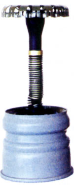
The missile itself has a familiar layout with the rocket motor placed in the middle, the warhead at the very rear, and the control surfaces and mechanism at the front along with the fuse at the tip. The missile uses a solid fuel motor, with four nozzles arranged radially. Flight stabilization is maintained via five pop-out tail fins with curved and angled surfaces to impart a slow spin onto the missile, while steering is accomplished by the two canard fins at the front. These are operated pneumatically, so the more corrections the gunner makes while the missile is mid flight, the less responsive the missile will be over time, though the gunner will have to be tracking a very difficult target like a helicopter for this to become noticeable.

Guidance is accomplished by the integrated 9S517 laser beam unit on the 1G46 sighting complex.
Missile Diameter: 125mm
Wingspan (Stabilizer Fins): 250mm
Shaped Charge Diameter: 105mm
Maximum Engaging Distance: 5000 m
Minimum Engaging Distance: 100 m
Hit Probability On Tank-Type Target Cruising Sideways At 30 km/h:
100 m to 4000 m = > 0.9
4000 m to 5000 m = > 0.8
Flight Distance Time:
5000 m - 17.6 s
4000 m - 11.7 s
3UBK14M
9M119M "Refleks-M"
The appearance of Refleks-M gave the T-80 the newfound ability to confidently destroy new heavy NATO tanks like the M1 Abrams. That is, until the M1A1 variant appeared in 1985.
The precurser warhead has a cone diameter of 64mm, essentially just as large as a 66mm LAW warhead, and almost equally as powerful. Unlike typical Western tandem warhead designs, the precurser warhead on the Refleks-M was deliberately made powerful enough to compromise the thick composite arrays on emerging NATO tanks before the main charge detonates.
Penetration:
700 - 750mm RHA (Without ERA)
650 - 700mm RHA (Behind ERA)
3UBK20M "Invar"
9M119
Thermobaric missile.
3UBK20M-1 "Invar-M"
With nothing but a decade's worth of technological enhancement, the Invar-M boasts a more powerful tandem warhead, while maintaining the same flight distance and with no real changes to the dimensions of the missile body. Aesthetically, it is identical to the Refleks missiles. Invar-M was introduced in the latter half of the 90's, and is currently in service.
Armour Penetration:
900 mm RHA (Without ERA)
850mm RHA (With ERA)
CO-AXIAL MACHINE GUN
The T-80 is equipped with the ubiquitous PKT general purpose machine gun as a supplementary coaxial weapon.

It is fired by the gunner using his hand grip controls. The commander may also cut in on the action and use the 6P7.S6.12 electric solenoid switch attached to the machine gun, or in the case of the T-80U, the trigger button on the PNK-4S control module.
The machine gun is mounted to the right of the main gun, and protrudes from a pill-shaped port which provides vertical space for gun elevation. Since it is mounted alongside the main gun, it receives all the benefits of the stabilization system.
The co-axial machine gun is only a limited solution to the infantry problem, especially if cover is available for them. In practice, the co-axial is only useful in very specific situations, and desireable only when HE-Frag shells are not suitable. In essence, the PKT(M) is more of a weapon of opportunity than anything else.
ANTI-AIRCRAFT MACHINE GUN

The T-80 continues the tradition of mounting an inclusive large caliber AAMG on the turret roof, but it does so in a rather curious way. Instead of a conventional ring or skate mount or perhaps a direct installation onto the rotating cupola, the T-80U's NSVT can be installed onto any one of three pedestals jutting out of the turret roof. There is one forward and slightly right of the commander's cupola, a rather stubby one immediately to its left, and another directly behind it for a total of three. Alternatively, there is another pedestal behind the gunner's hatch.

This unusual scheme has its own small advantages, of course, but for the most part, the system is more trouble than what it is worth. For one, the fixed installation of the machine gun limits the aiming sector to only about 90 degrees forward and slightly to the right, and that's with the commander leaning out of the hatch. To aim sideways, the commander must exit his hatch and sit out on the turret roof, open to all and sundry. Aiming backwards is not possible unless the machine gun is installed on the rearmost pedestal, which is not feasible when already in combat, as the machine gun itself already weighs 25 kg. The NSVT mount also includes a canvas belt catcher to prevent sections of belt from landing in front of the commander's sight aperture and obstructing it.


The NSVT itself is a respectably accurate, rapid-firing heavy machine gun chambered in the 12.7x108mm cartridge. It fires at the devastating cyclic rate of 700 to 800 rounds per minute, but at longer ranges, heavy machine guns generally just devolve to a "spray and pray" regiment, especially against fast-moving jet attack aircraft. Against slower attack helicopters, the NSVT may still prove marginally useful every now and then, especially if the attack helicopter in question has poor or no cockpit and fuselage protection like the AH-1 or AH-64. Firing at aerial threats is facilitated by a K-10T collimator sight attached to the machine gun cradle while firing at ground targets can be done with the K-10T collimator sight, but using the machine gun's original iron sights is more appropriate for the job.


For some strange inexplicable reason, the NSVT on the T-80 is fed with unusually voluminous 150-round boxes; an obvious point of merit compared to other tank-mounted AAMGs which are typically furnished with more modest 50-rounders, like on the T-72 and T-54. Transferring the 11 kg ammo boxes from the side of the turret to their special bracket on the left of the mount can be simplified by rotating the machine gun to the right, making it that much easier to haul them up.
1ETs29 Remote Weapons Station

In 1987, the all-new T-80UD received a new remotely controlled, electrically assisted machine gun mount integrated into a redesigned commander's cupola. It is independently vertically stabilized, and derives horizontal stabilization from the counterrotation mechanism of the cupola. The range of elevation permitted by the mount is extremely generous, spanning from -15° to +85°.
Aimed fire on ground targets is conducted using the PNK-4 combined sighting system through the eyepieces of the TNK-4S. The commander can shift from observation to shooting at the flick of a toggle switch, whereupon the reticle of the TKN-4S changes to a graduated one with suitable markings and the stabilizer for the NSVT mount is slaved to the sight. The commander is then able to use the sight elevation handgrip to operate the machine gun up and down by +20° and -4° down respectively.
If the commander wishes to shoot at something or someone at a greater height to him, he may use the PZU-7 anti-aircraft sight installed at the front left quadrant of the cupola. Using it disengages the machine gun from the TKN-4S, but the use of the thumbswitch is retained for aiming and firing. The sight has a maximum elevation of +70° and maximum depression of -5°.


Thanks to vertical stabilization, the commander has the ability to engage a wide range of targets while on the move. More specifically, both ground targets and low flying aircraft are potential targets, particularly helicopters flying at treetop level, enabling the tank to fight and flee at the same time.

The main merit of the new weapon system is of course the fact that the commander does not need to expose himself to fire the machine gun, thus isolating him from harm, but another less obvious but equally noteworthy improvement is the deletion of the frontmost mounting pedestal, thus giving the commander a free, unobstructed view of the front-right of the turret.
On the modern battlefield in the modern world, the utility of the normally proprietary anti-aircraft weapon is extremely limited. Current trends in anti-insurgency warfare have demoted the machine gun to a marginally useful tool of suppression, and though the 12.7mm caliber is more adept than the 7.62mm caliber at destroying light cover like adobe walls and tree stumps, heavy machine guns are generally too inaccurate at the distances at which it surpasses the general purpose machine gun in such value. That, in combination with the low ammunition reserves owing to the large size of the cartridge, has led to the necessary extinction of the heavy machine gun as a native weapon system on tanks. In realization of this fact, the new T-14 mounts not an NSVT or KORD but a PKTM general purpose machine gun fed with 500 rounds in a single box, as compared to the 150 loaded for the NSVT on the T-80, and the 50 for the M2HB on the Abrams. In this regard, the T-80 joins fellow Cold War era tanks in obsolescence.
PROTECTION

There is no doubt that it was the T-80 series that had the most sophisticated sighting systems and the best firepower, and the T-80s were one of the fastest tanks on Earth to boot, but nothing is perfect. For the T-80, the crux of the matter is the lackluster effort made in utilizing the best glacis armour available at the time, and the turret armour was surpassed by the T-72B in 1983. Regardless, the members of the T-80 family still had a warranty of virtual invulnerability to the vast majority of weapons deployed by NATO with a superiority margin of several years' worth of technology.
And let's not forget to mention that the secret to not blowing up is to not get seen. The T-80 was equally as short as its big brother the T-64 and its cousin the T-72, though it did get a little taller when the new Object 476 turret was fitted in 1985. Otherwise, the T-80 and T-80B from 1976 and 1978 respectively were both nearly as short as the novel Stridsvagn 103 by a margin of just a few centimeters. And one of the features that made the Strv. 103 so attractive to the Swedes was, of course, its low silhouette.

Still, getting seen is inevitable, and not getting seen might not even be possible sometimes, so when the tank does get hit, the only thing that's worth anything is the steel between the crew and certain death.
T-80
Not only were the very first T-80s from 1976 visually indistinguishable from the earlier T-64A, they also shared a great many components and even had identical glacis armour geometry and configurations. Just as with the T-64 and T-72, the steel used in the array had a hardness of between 290 and 340 BHN. The entire array measures 205 mm in actual thickness, but the 68° slope multiplies this figure to 547 mm in relative thickness. The configuration is as follows:
80 mm RHA > 105 mm STEF > 20 mm RHA
The first steel plate does most of the work by eroding and breaking up the penetrator, and the STEF layer assists by arresting the broken up penetrator, which prevents it from forming a plug or continuing to experience adiabatic shearing due to the radically different density and the shift from a granular structure (steel) to a bidirectional fibrous matrix (STEF). The high-strength fibers perform the same function as kevlar in a ballistic vest. The third and last layer absorbs any residual chunks of the penetrator, but of course, the hardness of the plate and the very high incidence angle repeats the same deflecting effect that the penetrator will have experienced when it first impacts the sloped first plate, so in essence, the penetrator is deflected twice throughout its sojourn into the armour array.
*STEF is a certain type and grade of glass-reinforced textolite, a material consisting of layered sheets of plain-woven glass textile suspended in an epoxy resin matrix. It is nearly identical to fiberglass, except that it is stronger.
In 1979, the original T-80 underwent a modernization program to bring it up to the level of the T-80B, which sported a new and better optimized glacis array without any internal modification or dismantling of the tank of any kind. As a result, it was decided to weld a 20mm hard steel appliqué plate to supplement the base armour. The 20mm armour plate weighs approximately 0.75 metric tons, and came pre-fabricated to the depot, where it could be installed as part of regular scheduled maintenance, along with a few other minor things added as part of the modernization program.
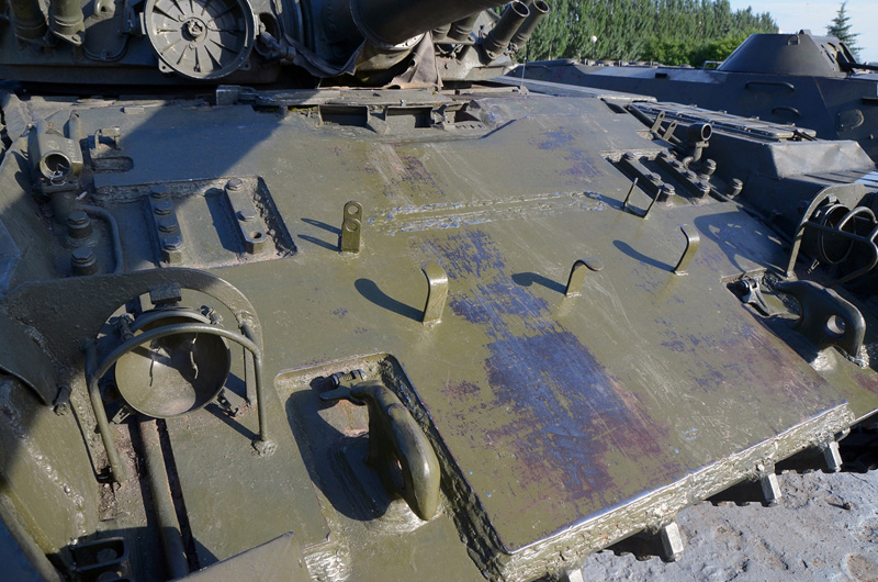
The extra armour plate probably had a hardness of around 400 to 450 BHN. This greatly improved the deflection factor against kinetic energy penetrators, even those with improved armour piercing tips specially designed to deal with steeply sloped armour - the M111 Hetz, for instance. In addition to that, the difference in hardness between the appliqué plate and the base armour created a dual hardness armour (DHA) regime. A plethora of military records, documents and reports in conjunction with research papers available in the public domain have all suggested or concluded that DHA arrays present very significant improvements in protective value relative to the gain in thickness, second only to THS (Triple Hardness Armour). All of these factors have been taken into account in the protection values below.
KE
UPPER GLACIS: ~360mm RHAe ... ~460mm RHAe (Vanilla ... with Applique)
LOWER GLACIS: 181mm RHAe
HEAT
UPPER GLACIS: ~450 mm RHAe ... ~550 mm RHAe (Vanilla ... with Applique)
LOWER GLACIS: 181 mm RHAe
T-80B
While the original glacis armour configuration was more than enough to contend with perhaps all 105mm ammunition of the APDS variety found on the other side of the Berlin Wall, by 1976, the design was already teetering on the brink of obsolescence in light of recent Western research into APFSDS technology. Therefore, in 1978, the layout received a belated update for the new T-80B using the same materials, with only a few minor tweaks in thicknesses. The new array is copied from the T-72A, which achieved IOC in 1976. The configuration is as follows:
60mm RHA -> 105mm STEF -> 50mm RHA
Due to the decreased thickness of the steel components, it became possible to increase their hardness to around 340 BHN.
By 1983, recent revelations on newly emerging 105mm APFSDS technology - namely that the Israeli M111 Hetz had better than expected performance - and the need to bring the standard of protection up to the level of the new T-80BV with no internal modification and at minimal expense, it was decided to yet again outfit the glacis with an appliqué armour plate just as before. However, this time, the plate was only just shy of half the thickness at only 16 mm. It is most likely that the M111 was discovered to be able to perforate the "60-100-50" array at very short distances, hence the incredibly minor effort spent on uparmouring it. The author infers that this is most likely due to the appearance of the 120mm DM13 APFSDS shell in 1979, which turned out to not be that impressive in the end, but they probably didn't know that in 1982.
KE
UPPER GLACIS: ~400 mm RHAe ... ~460 mm RHAe (Vanilla ... with Appliqué)
LOWER GLACIS: 181 mm RHAe
HEAT
UPPER GLACIS: ~500 mm RHAe ... ~560 mm RHAe (Vanilla ... with Applique)
LOWER GLACIS: 181 mm RHAe
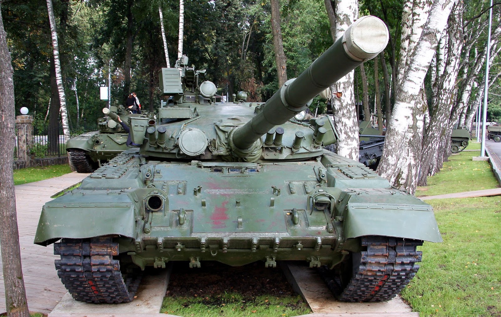
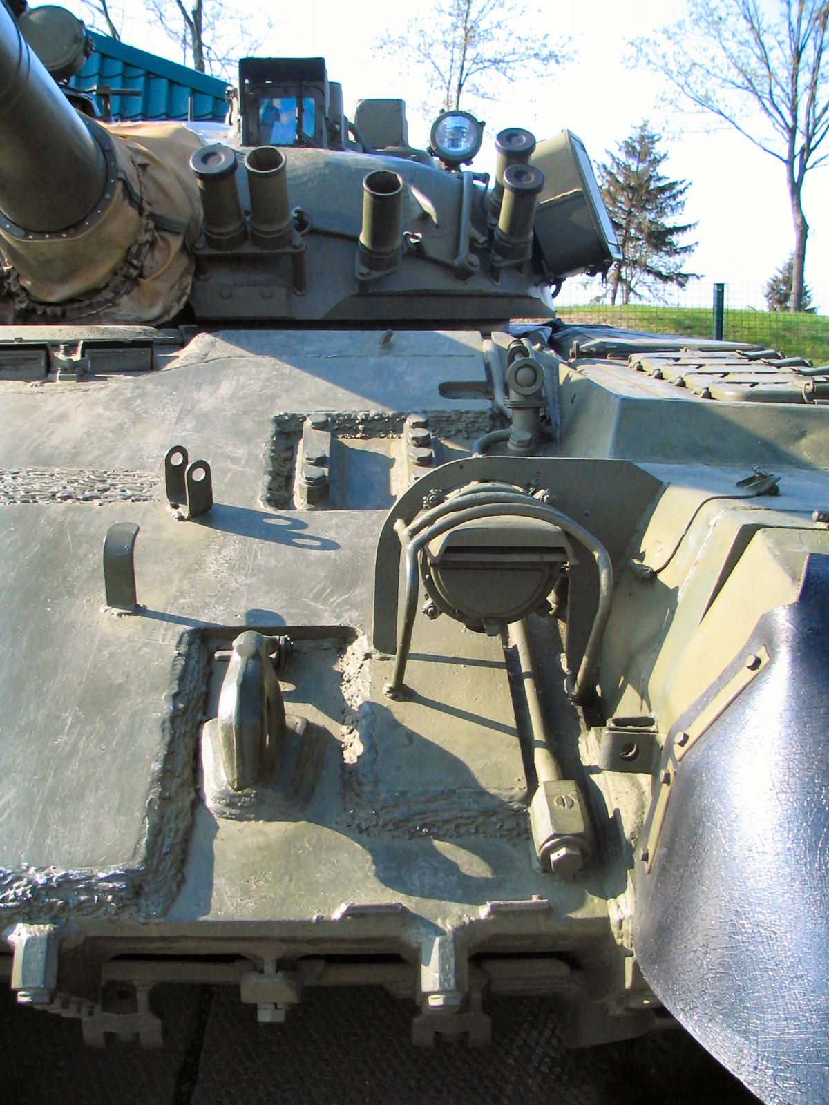
All in all, the T-80B with the appliqué armour plate should be able to shrug off 105mm APFSDS shells like the M774 and M833 at maybe around 1 km, and also early 120mm APFSDS like the DM13 at the same distance, but probably not the DM23, which was basically an elongated DM13. Without the extra armour, the T-80B is most likely vulnerable to all of these munitions at a distance of up to 2 km, but still totally invulnerable to 105mm APFSDS introduced in the mid-70's like the M735.
T-80BV
In 1982, the newly introduced T-80BV came endowed with a heavier, but more effective double sandwiched laminate array design for the upper glacis. Instead of a single layer of STEF between two steel plates, the new array is composed of two thinner layers of STEF sandwiched between three steel plates.
Thanks to the implementation of new thermomechanical processing techniques in tandem with the inherent simplicity of applying such heat treatments to thinner steel plates, the steel used in the T-80B's glacis is most likely of the extremely hard variety. The high hardness of the plates combined with the steep slope of the glacis grants not only better overall protection, but adds the additional benefit of increased deflection when attacked by APDS and even APFSDS munitions.
This new layout could offer comprehensive protection from the latest 105 mm APFSDS shells including the M111 Hetz and the DM23 (105) based upon it, M774, M833, OFL105F1, and also the 120mm DM13 APFSDS shell.
50 mm RHA -> 35 mm STEF -> 50 mm HHS -> 35 mm STEF -> 50 mm RHA
KE
UPPER GLACIS: ~533 mm RHAe
LOWER GLACIS: 181 mm RHAe
HEAT
UPPER GLACIS: ~600 mm RHAe (?)
LOWER GLACIS: 181 mm RHAe
Kontakt-1
The addition of Kontakt-1 ERA armour added just under 1.2 tons to the original weight of the tank.

Mounting the blocks is extremely easy, but tedious. Each one is bolted onto a tinny spacer mounted all over the surface of the hull and turret. The ease of installing and replacing the blocks meant that the entire modification could be done as part of regular scheduled maintenance. However, simplicity comes at a price in this case. The rubberized side skirts are rather fragile, and can be quite easily knocked off when the tank is travelling through densely wooded areas, or perhaps traversing obstacles in urban sprawl. With the added burden of a few dozen Kontakt-1 blocks mounted onto it, it only gets easier to accidentally knock the side skirts off.
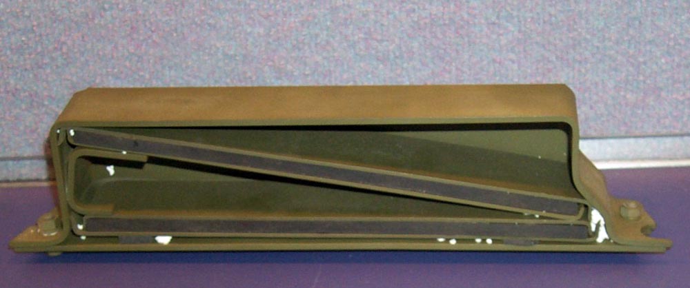

The operation of Kontakt-1 is quite simple, utilizing two angled explosive plates to disrupt cumulative jets through high-velocity shockwaves and the separation of the steel sheets which comprise the block itself .
Each Kontakt-1 block consists of two 4S20 explosive elements, which are plastic explosives packed into a flat steel plates. The mass of the explosive material in each element is 260 grams, equivalent to 280 grams of TNT. They have a low sensitivity to ensure that they can survive being hit by machine gun fire without detonating prematurely. The weight of each block is 5.3kg, and a full set covering the entire tank weighs approximately 1.2 tons.
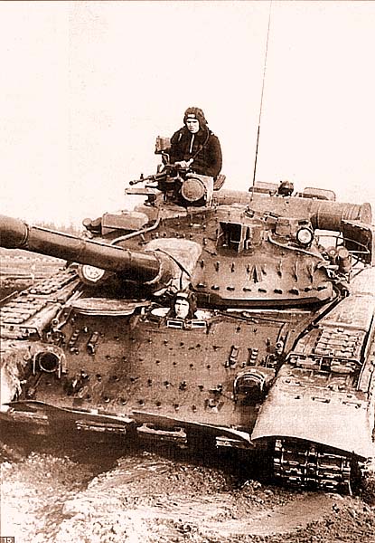

The turret modules are mounted on a spacer frame set at an angle of 45°.
T-80U
The T-80U carried over the 5-layer glacis array from the T-80BV, so there's not much to talk about here without getting into the Kontakt-5 reactive armour integrated with the tank. What's more interesting is the installation the T-80A turret, which had a very distinct aesthetic profile.
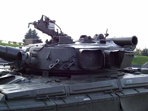
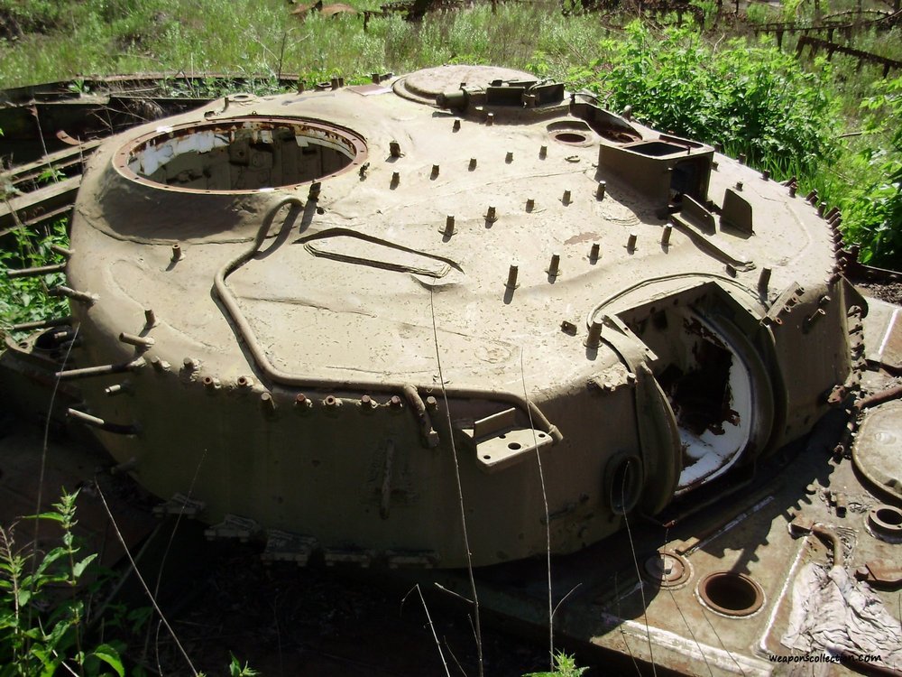
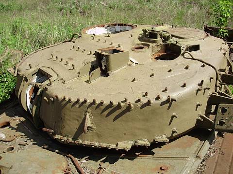
Kontakt-5

Though even the best 105mm APFSDS shells and the most powerful guided missiles had already been successfully nullified by the introduction of new composite armour and Kontakt-1 explosive reactive armour, there was still the 120mm threat to consider. 120mm ammunition of the early 80's weren't much of a short term threat, but it was clear that the new Rheinmetall invention had great potential. While the M1 Abrams was not armed with the M256 for which it was famous for until the M1A1 upgrade in 1985, the Leopard 2 had achieved IOC in 1979 and had already grown into a thousand-strong contingent by late '84. The folks at NII Stali did not twiddle their thumbs idly while news of the new NATO tanks trickled in, and thus, Kontakt-5 was introduced in 1985 as an integral component of the new T-80U.
Coverage on the glacis is fantastic, but not so much for the turret, which is totally unprotected on either side of the gun mantlet. This was done in the interest of the driver's convenience when ingressing and eggresing his station. Unfortunately, once he slips in, there is an increased possibility that he will never get to get out ever again.
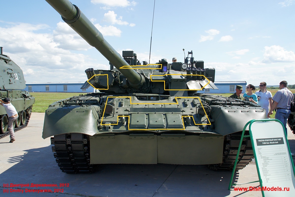
Still, the total size of the protected area is quite decent, especially around the upper glacis, which happens to be the center point of the tank's silhouette, making it the most often damaged part of the tank assuming that the tank is advancing towards the enemy on flat open ground. However, British trialing had long ago concluded that it is the turret that sustains the majority of hits when engaging in tank-on-tank combat. This is because the lower third of the tank is usually not visible to the enemy due to tall grass and undergrowth, making the turret of the tank the de facto center mass .
How Kontakt-5 Works
Kontakt-5 works on the basis of explosively-propelled flyer plates that attack an offending projectile and destroys it before it enters the base armour. Against HEAT warheads, the general working principle of Kontakt-5 remains the same as that of bulging armour. The cumulative jet will be subjected to lateral forces which will break it up and disperse it, though the hypervelocity tip will invariably still continue forward; Kontakt-5 cannot destroy cumulative jets completely, but it can certainly render them harmless with an efficacy similar, but slightly lower than that of Konkakt-1. For kinetic energy projectiles, Kontakt-5 operates thusly: By utilizing explosively-propelled flyer plates, projectiles can experience catastrophic destruction from being subjected to intolerable lateral forces, thereby conditioning the projectile for defeat by the main armour. The defeat mechanism for KE projectiles is illustrated below:

Kontakt-5 is backwards moving plate, meaning that the plate flies into the path of the penetrator. A forwards moving plate as shown in the illustration above is a plate that flies in the same direction as the penetrator, so the illustration is incorrect, but enlightening nonetheless. The higher the angle of incidence between the penetrator and the Kontakt-5 module, the more pronounced the effect will be.
Kontakt-5 works on the basis of explosively-propelled flyer plates that attack an offending projectile and destroys it before it enters the base armour. Against HEAT warheads, the general working principle of Kontakt-5 remains the same as that of bulging armour. The cumulative jet will be subjected to lateral forces which will break it up and disperse it, though the hypervelocity tip will invariably still continue forward; Kontakt-5 cannot destroy cumulative jets completely, but it can certainly render them harmless with an efficacy similar, but slightly lower than that of Konkakt-1. For kinetic energy projectiles, Kontakt-5 operates thusly: By utilizing explosively-propelled flyer plates, projectiles can experience catastrophic destruction from being subjected to intolerable lateral forces, thereby conditioning the projectile for defeat by the main armour. The defeat mechanism for KE projectiles is illustrated below:


The mass of each cell is 280 grams, equivalent to 330 grams of TNT. It is possible to replace these cells with 4S23 cells from the Relikt ERA system, since they are exactly identical in dimensions. Look:

From left to right: 4S20, 4S24, 4S23, 4S22 (for Kontakt-1, Relikt, and Kontakt-5)
4S23 cells are hypersensitive when subjected to shocks above a certain threshold, while remaining stable when subjected to shocks under it, and they are more powerful to boot. This means that 4S23 cells have a greatly reduced reaction time, meaning that the explosives have a higher reaction rate, allowing the modules to activate near-instantaneously, giving them the ability to disrupt a greater portion of a cumulative jet or intercept a kinetic energy projectile sooner. It is entirely possible that newer-production T-90A and T-72B3 tanks have been supplied with 4S23 instead of the normal 4S22, and that 4S22 is being phased out. However, this is speculation and speculation only.
The mass of each cell is 280 grams, equivalent to 330 grams of TNT. It is possible to replace these cells with 4S23 cells from the Relikt ERA system, since they are exactly identical in dimensions. Look:
4S23 cells are hypersensitive when subjected to shocks above a certain threshold, while remaining stable when subjected to shocks under it, and they are more powerful to boot. This means that 4S23 cells have a greatly reduced reaction time, meaning that the explosives have a higher reaction rate, allowing the modules to activate near-instantaneously, giving them the ability to disrupt a greater portion of a cumulative jet or intercept a kinetic energy projectile sooner. It is entirely possible that newer-production T-90A and T-72B3 tanks have been supplied with 4S23 instead of the normal 4S22, and that 4S22 is being phased out. However, this is speculation and speculation only. |
| From left to right: 4S20, 4S24, 4S23, 4S22 (for Kontakt-1, Relikt, and Kontakt-5) |
There are two variants of Kontakt-5 employed on the T-80. The glacis modules are set at 68 degrees to the vertical plane, and that fact alone makes them extremely potent. However, the turret modules are set at only 50 degrees to the vertical plane. To compensate for this, the modules on the turret are of a bidirectional design. But first, let us examine the upper glacis of a T-80U.
There are two variants of Kontakt-5 employed on the T-80. The glacis modules are set at 68 degrees to the vertical plane, and that fact alone makes them extremely potent. However, the turret modules are set at only 50 degrees to the vertical plane. To compensate for this, the modules on the turret are of a bidirectional design. But first, let us examine the upper glacis of a T-80U.
GLACIS
 |
| Flyer plates removed |
Loading and reloading the modules is an extremely simple affair, as long as you have a hex wrench at hand. Each module is filled with eight 4S20 explosive cells, arranged in a pattern of four, stacked two deep.


TURRET
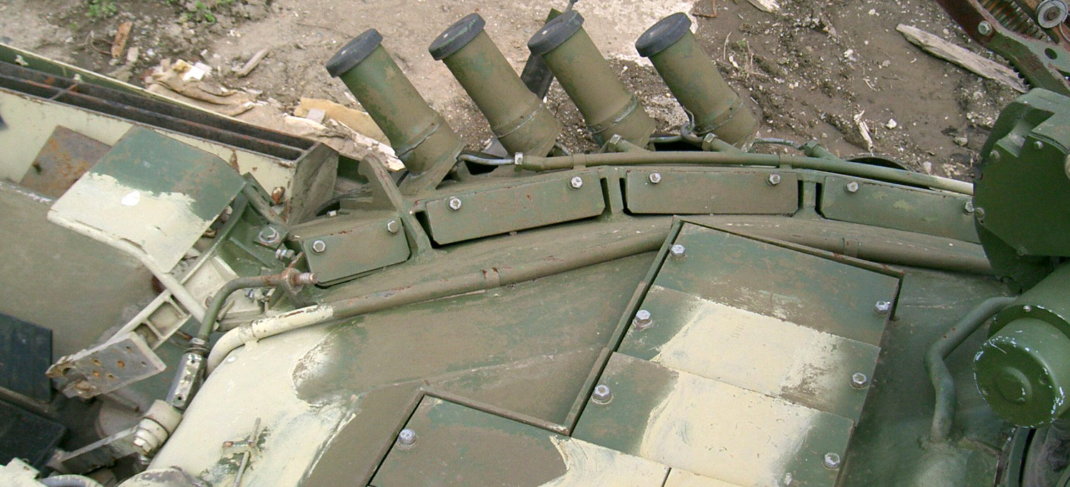
The turret modules are installed with a slope of 50°.
Loading and reloading the turret modules are equally painless. However, the flyer plates for the turret modules are not bolted onto a fixed housing. Rather, they are welded to the walls of the support structure frame. As such, replacing the turret blocks flyer plates is less straightforward than replacing the ones on the glacis, as doing so requires welding equipment and subsequently results in a longer turnaround time.
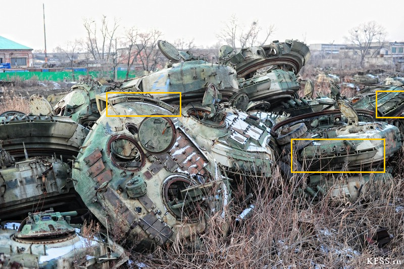
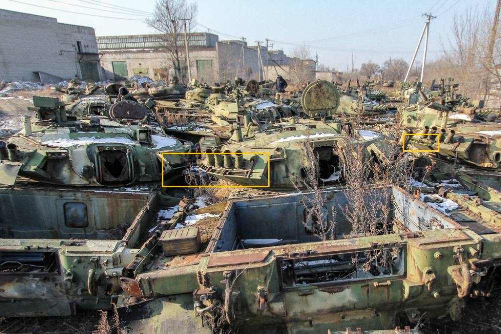
Click to enlarge
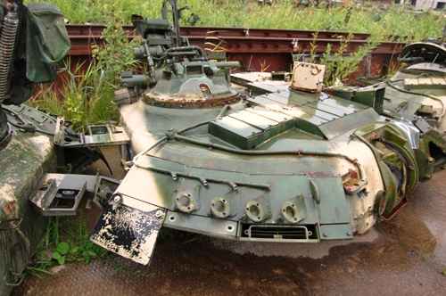
Each turret module is composed of a single backwards-flying flyer plate, with a robust steel box welded to it from behind to contain four 4S22 explosive cells - two cells side by side, stacked two-deep to make four. The thick walls of the steel box act as a forwards-flying flyer plate, and the walls of the box welded to it act as a backwards-flying flyer plate.

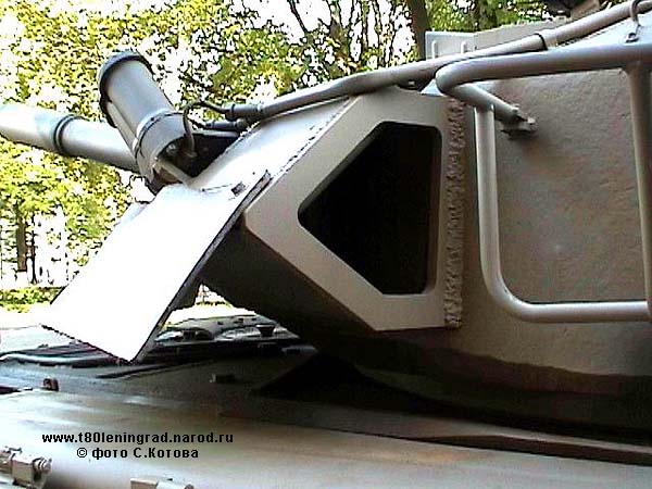
This is congruous with the fact that the Kontakt-5 modules on the T-72B obr. 1989 have no significant amount of air space behind them, but they are set at a much steeper slope of 68 degrees instead.

For present day kinetic energy penetrators, bypassing the modules is impossible. The M829A3, for instance, was designed to travel at an unusually low speed so that it would not produce enough shock to activate the explosive material within, but even then, the success rate of this method is apparently only about 50% at most. The solution to the M829A3 problem would be simple - replace the explosive modules with more sensitive ones. No modification would be required. Kontakt-5 was originally designed to use 4S22 explosive elements. These are very potent plastic explosives sealed in a flat sheet steel box, pictured below.

For present day kinetic energy penetrators, bypassing the modules is impossible. The M829A3, for instance, was designed to travel at an unusually low speed so that it would not produce enough shock to activate the explosive material within, but even then, the success rate of this method is apparently only about 50% at most. The solution to the M829A3 problem would be simple - replace the explosive modules with more sensitive ones. No modification would be required. Kontakt-5 was originally designed to use 4S22 explosive elements. These are very potent plastic explosives sealed in a flat sheet steel box, pictured below.
Kontakt-5 on the T-80 is composed of a welded steel body and explosive cells, topped off with a bolt-on cover plate. The steel body acts to contain the immense pressure from the detonation of the explosive cells and to prevent premature damage from machine gun and autocannon fire, and the front facing of the steel body is the flyer plate. It is made of high hardness steel. The front plate measures approximately 15mm, or 40mm with the angling of the glacis accounted for. Each Kontakt-5 module contains 8 4S22 explosive cells, and so each module has the explosive power of about 2.64kg of TNT. Once the module is activated, the 8 cells detonate, producing so much pressure that the welded top is propelled (or rather, violently blown off) at tremendous speed away from the glacis. This means that the 15mm high hardness plate is attacking the penetrator at an angle of 68 degrees relative to its flight path, thus completely destroying the penetrator save the front end, which will most definitely pass through because of the lengthy reaction time that Kontakt-5 suffers from. Aside from the natural relative slowness of the explosive cells, the flyer plate, which is welded onto the partitions between each module, is secured firmly such that pressure will build up inside the module for a few milliseconds longer before the flyer plate can finally detach and actually "fly". Nevertheless, Kontakt-5 completely immunizes the T-80U from shells like the M829, M829A1 and M829A2 and DM43 at combat ranges.
Because of the thickness of the front plate, Kontakt-5 modules have scant, but a meaningful chance of survival from the miniature precurser shaped charges on some ATGMs, specifically the TOW 2A (whose precurser shaped charge is a measly 30mm in diameter, with a very small explosive punch and no wave shaper). Even if the precursor charge does set off Kontakt-5, its detonation will not occur as quickly as if it was hit by a full-power warhead. This delay may allow the flyer plate to intercept the primary warhead after all, despite the precursor. Besides that, the modules are protected from all forms of heavy machine gun fire as well. Their hardness, thickness and steep sloping also shield them from some forms of autocannon fire at extended ranges, including 20mm APDS and 25mm APDS. The welded rear may also act as applique armour if the module is spent, thanks to its thickness, which is almost as much as the 16 milimeters of applique armour on the T-72 Ural and T-72A.
However, all things come at a cost. In the case of Kontakt-5, its high explosive content and power is also its biggest drawback, as it is perfectly possible for the activation of one module to set off another. Now, the photo below doesn't actually show the aftermath of this phenomenon. It's just for illustration.

It's quite obvious in the case above that an APFSDS shell struck the edge between the upper and lower modules, which set both off and didn't do very much to the penetrator.
Kontakt-5 on the T-80 is composed of a welded steel body and explosive cells, topped off with a bolt-on cover plate. The steel body acts to contain the immense pressure from the detonation of the explosive cells and to prevent premature damage from machine gun and autocannon fire, and the front facing of the steel body is the flyer plate. It is made of high hardness steel. The front plate measures approximately 15mm, or 40mm with the angling of the glacis accounted for. Each Kontakt-5 module contains 8 4S22 explosive cells, and so each module has the explosive power of about 2.64kg of TNT. Once the module is activated, the 8 cells detonate, producing so much pressure that the welded top is propelled (or rather, violently blown off) at tremendous speed away from the glacis. This means that the 15mm high hardness plate is attacking the penetrator at an angle of 68 degrees relative to its flight path, thus completely destroying the penetrator save the front end, which will most definitely pass through because of the lengthy reaction time that Kontakt-5 suffers from. Aside from the natural relative slowness of the explosive cells, the flyer plate, which is welded onto the partitions between each module, is secured firmly such that pressure will build up inside the module for a few milliseconds longer before the flyer plate can finally detach and actually "fly". Nevertheless, Kontakt-5 completely immunizes the T-80U from shells like the M829, M829A1 and M829A2 and DM43 at combat ranges.
Because of the thickness of the front plate, Kontakt-5 modules have scant, but a meaningful chance of survival from the miniature precurser shaped charges on some ATGMs, specifically the TOW 2A (whose precurser shaped charge is a measly 30mm in diameter, with a very small explosive punch and no wave shaper). Even if the precursor charge does set off Kontakt-5, its detonation will not occur as quickly as if it was hit by a full-power warhead. This delay may allow the flyer plate to intercept the primary warhead after all, despite the precursor. Besides that, the modules are protected from all forms of heavy machine gun fire as well. Their hardness, thickness and steep sloping also shield them from some forms of autocannon fire at extended ranges, including 20mm APDS and 25mm APDS. The welded rear may also act as applique armour if the module is spent, thanks to its thickness, which is almost as much as the 16 milimeters of applique armour on the T-72 Ural and T-72A.
However, all things come at a cost. In the case of Kontakt-5, its high explosive content and power is also its biggest drawback, as it is perfectly possible for the activation of one module to set off another. Now, the photo below doesn't actually show the aftermath of this phenomenon. It's just for illustration.
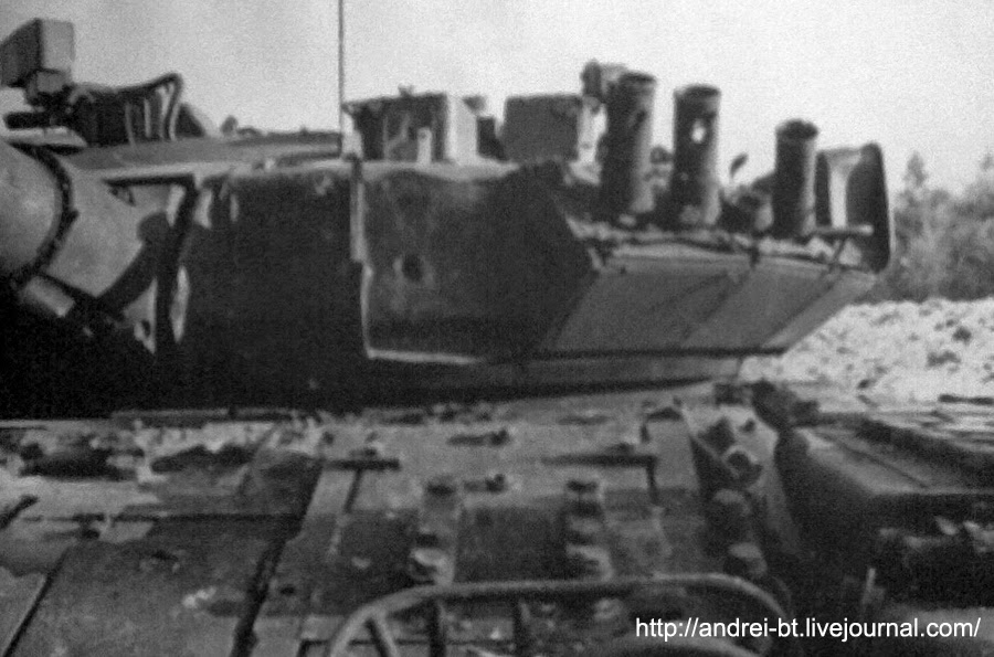
It's quite obvious in the case above that an APFSDS shell struck the edge between the upper and lower modules, which set both off and didn't do very much to the penetrator.
SIDE HULL
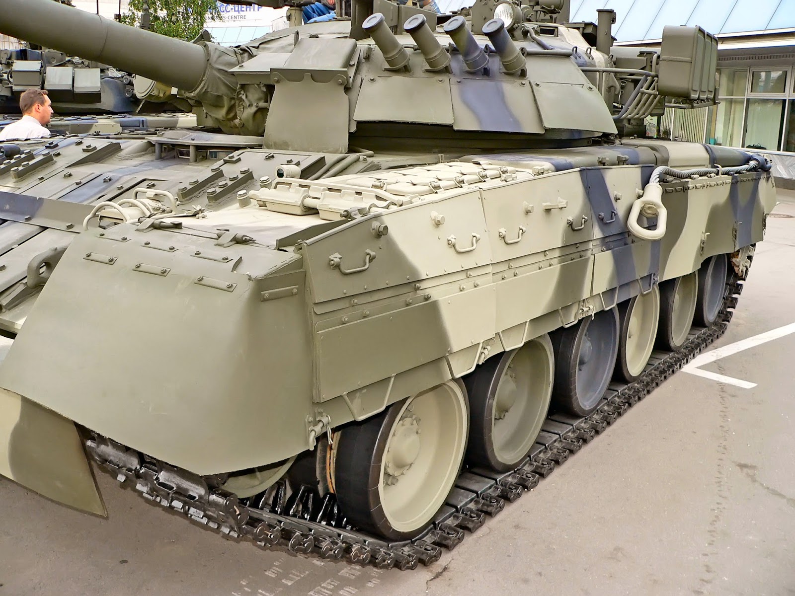
Without effective measures for protecting the sides of the hull, the tank's speed and agility will be for nothing. 80 mm of steel, even angled at 70 degrees, isn't really worth much against any quasi-modern shaped charges or long-rod penetrators. With Kontakt-5 and about a meter and a half of air space, though (depending on the incidence angle), the odds of survival suddenly doesn't seem that bad. With these side hull modules, the T-80 should be immune to hits from any 105mm APFSDS shell within a 70° frontal arc, but this probably goes down to a 60° to 40° arc for earlier 120mm APFSDS. This should include the DM13, DM23, M829 and M829A1.
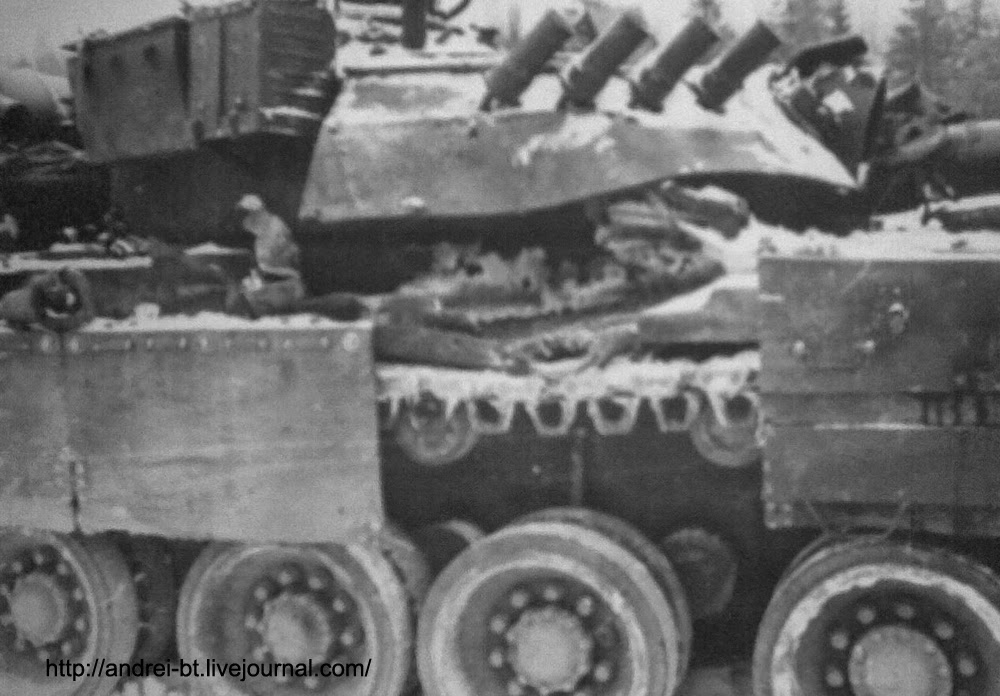
ROOF
Besides front facings of the turret, the upper glacis and the side hull, the roof of the turret is also partially protected by proprietary miniature blocks.

FIREFIGHTING
3ETs11-2 "Iney" Firefighting System
To prevent the spreading of internal fires in the engine and crew compartments, the 3ETs11-2 "Iney" halon gas quick-acting firefighting system was installed, with the driver-mechanic as the primary operator. The system can operate in two modes; automatic and semi-automatic. In the automatic mode, the system reacts immediately to a fire in either the crew compartment or the engine compartment and acts upon the flame regionally, meaning that the system activates specific fire extinguisher nozzles to put out the flame, as opposed to just flooding the entire compartment. In the semi-automatic mode, the system can still automatically detect a fire but instead of immediately activating the fire extinguishers, the driver-mechanic is alerted via the P11-5 control and signal unit placed just in front of him. The decision as to what the next course of action should be is deferred to him.
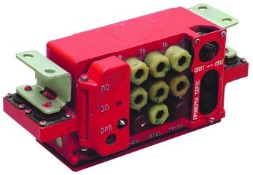 |
| P11-5 |
There are 12 TD-1 thermal sensors strategically placed in the engine compartment and crew compartment. The ones in the crew compartment are attached just above the floor of the hull, and aimed mostly at the floor. You can see one of them in the picture below, just right of the three fire extinguishers attached to the 3ETs11-2 system.
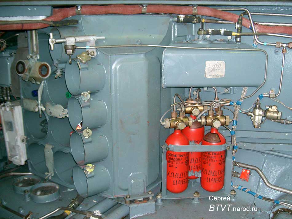
The firefighting system reacts regionally when a rise of temperature to 150°C is detected in the crew compartments and engine compartments.
The three PPZ fire extinguishers are equipped with electrically triggered special quick release valve heads. The PPZ extinguishers use R-114B2 compound, also known under the designation Halon 2402. It is very effective against any class of fire, but the tradeoff is that inhaling large quantities of it in a confined space (the inside of a tank, for example) is a huge health risk. It is advised to immediately throw open all hatches and partially exit the tank upon activation of the PPZ fire extinguishers.
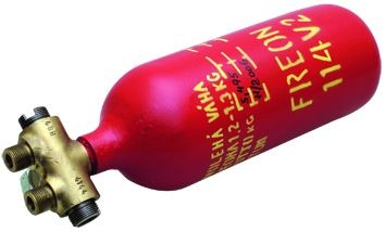
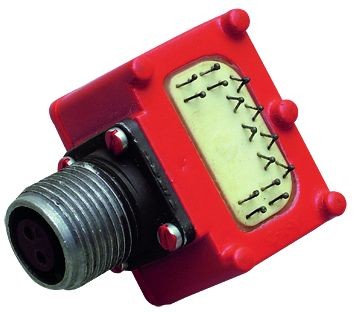
Two handheld OU-2 carbon dioxide fire extinguishers are also provided to supplement the automatic fire extinguisher system. If the TD-1 fire detectors fail to respond (usually in the case of small flames), then these will be the only firefighting tools available to the crew, aside from manually activating the PPZ fire extinguishers via the driver's control box. Carbon dioxide fire extinguishers are suitable on Class B and C (fuel and electrical fires), so they are right at home inside a tank. CO2 fire extinguishers are also more directional that halon extinguishers, so the user can starve a fire of oxygen quite effectively within the confines of the tank. Using the OU-2 extinguishers might be a more appealing option to activating the 3ETs11-2 system, since your chances of asphyxiating is somewhat lower.

SELF ENTRENCHMENT
If a company of T-80s were called upon to defend a certain sector out of the blue, and there isn't any time to create proper fortifications, the crew may create their own cover using the dozer blade installed on the lower glacis.

On flat, dry terrain, it can take up to 20 minutes to dig a tank-sized dugout, but on uneven soil, it can take as little as 5 minutes to do the same. For maximum stealthiness, camouflage netting and some improvisation is usually necessary for a proper disguise.
However, because of the T-80's turbine engine, it is extremely ill-suited for static defence, seeing how the engine guzzles nearly as much fuel while the tank is immobile as when it is going at full speed. Because of this, it may not be able to sustain a counterattack when the moment comes.

SMOKESCREEN
The secret to not getting blown up is to not get hit, and the secret to not getting hit is to not be seen. To that end, the T-80 is equipped with a smoke grenade system to shield it from prying eyes, but unlike prior Soviet tanks, the T-80 is unable to generate a fuel-based smokescreen from its engine, for fear of a potentially explosive result.
902V Tucha
The "Tucha" smoke grenade dispersal system was universal between all Soviet armoured vehicles invented during the 70's, and was subsequently retrofitted to vehicles made before that. For some strange reason, the gunner - and not the commander - has access to the sole control panel for firing the grenades.
There are three variations of grenade layouts featured on the T-80 series. The T-80, T-80B and T-80U had their smoke grenades arranged on the front turret cheeks, which was rather paradoxical, because if you got hit and wanted to hide yourself, the last thing you wanted was for your smoke grenades to be blown off...
The T-80 and T-80B had a bank of five launcher tubes on the left hand side turret cheek, and only three launcher tubes on the right hand side, due to the L-4 spotlight being in the way.
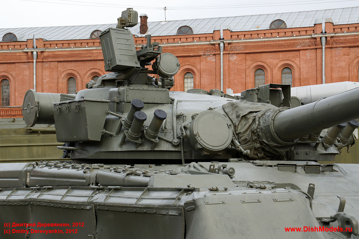
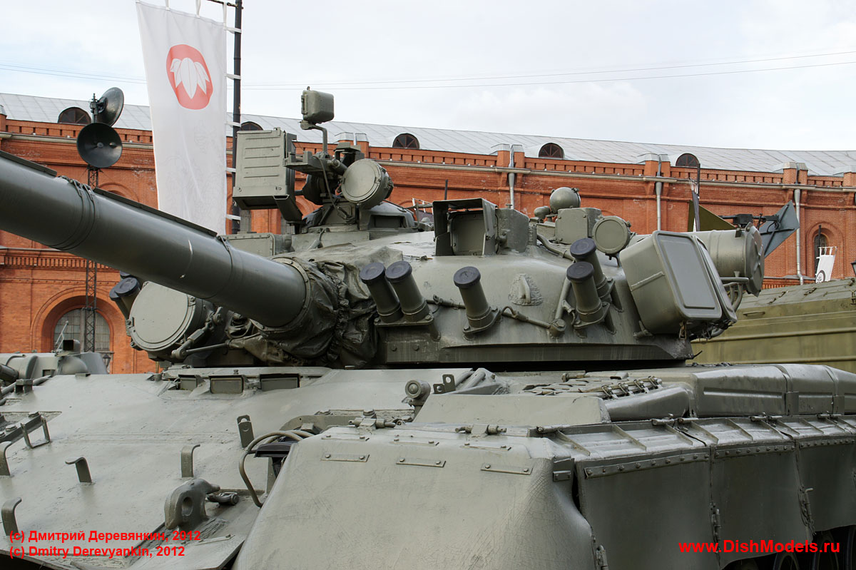
For the T-80BV, it was necessary to cluster the launcher tubes at the sides of the turret due to the impermanent nature of Kontakt-1. The earlier T-80BV with the T-80B turret and the late model T-80BV with the T-80U turret share the same configuration.
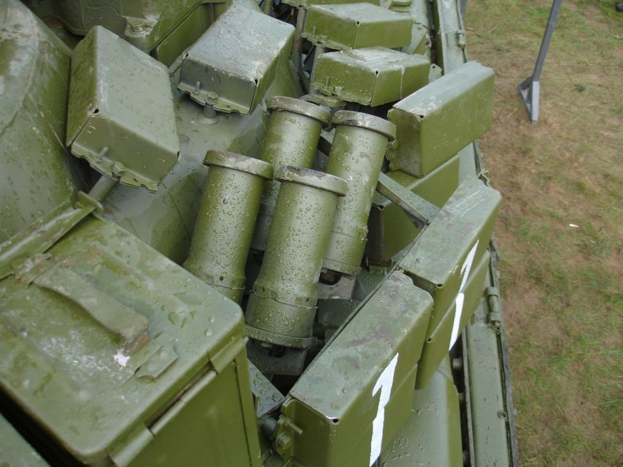
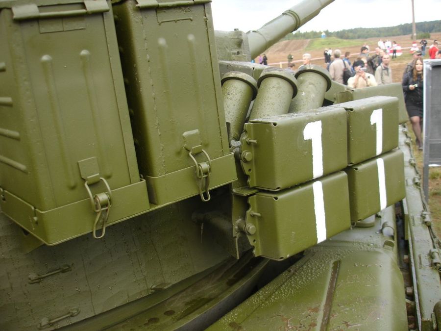
The launcher tubes on the T-80U were equally distributed, four per turret cheek. Since they are installed directly atop the Kontakt-5 modules, it's not hard to imagine what would happen to them if they got hit.
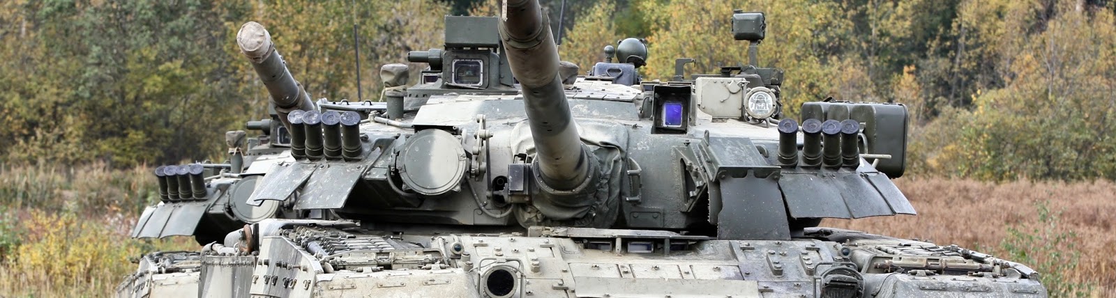
3D6
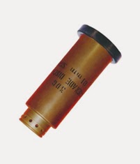
3D17
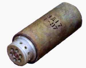

NBC PROTECTION
Nuclear annihilation was a very real existential threat during the Cold War, and even more so during the 70's and early 80's; a period widely regarded as the peak of hostilities. Facilitating the crew's survival in the event of a nearby atomic blast or after one is the GO-17 NBC protection suite.
Besides the more active part of the tank's anti-contamination system, the interior walls are lined with an anti-radiation material.
The liner is composed of borated polyethylene - a type of high-density polyethylene infused with boron - woven into fibers and made into sheets, which are then laminated and molded to fit around the curves of the tank using a heat gun, and then topped off with some sort of resin for weather protection. Boron is known to be extremely effective at capturing neutrons thanks to its large absorption cross section, making it suitable for use as radiation shielding. The fibrous construction of the sheets and the lamination process also makes it a suitable spall liner not dissimilar to early flak vests that used woven nylon plates.
Unlike the T-72 and T-64 series of tanks, the T-80 never got any external anti-radiation cladding.
MINE CLEARANCE
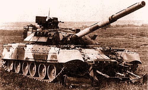
The mounting brackets on the upper glacis glacis are compatible with the KMT-6,
Th indiscriminately scoop up any mines, buried or unburied, anti-tank or anti-personnel, and shoves it to the side, creating a narrow mineless path for the tracks. This is fine... for the tank with the plow, which would be leading the crossing of the minefield as the only one of two in its company. For everyone else following behind, they can follow by driving on the track marks of the lead tank, but this is not possible in marshy and swampy ground, as doing so will lead to the tracks overpenetrating the soil, losing traction and getting stuck.
The ploughs can't reach anti-tank mines buried deeper than 8 or so inches, but this is fine, since the pressure exerted by the tracks probably won't be enough to set them off anymore.

DRIVER'S STATION
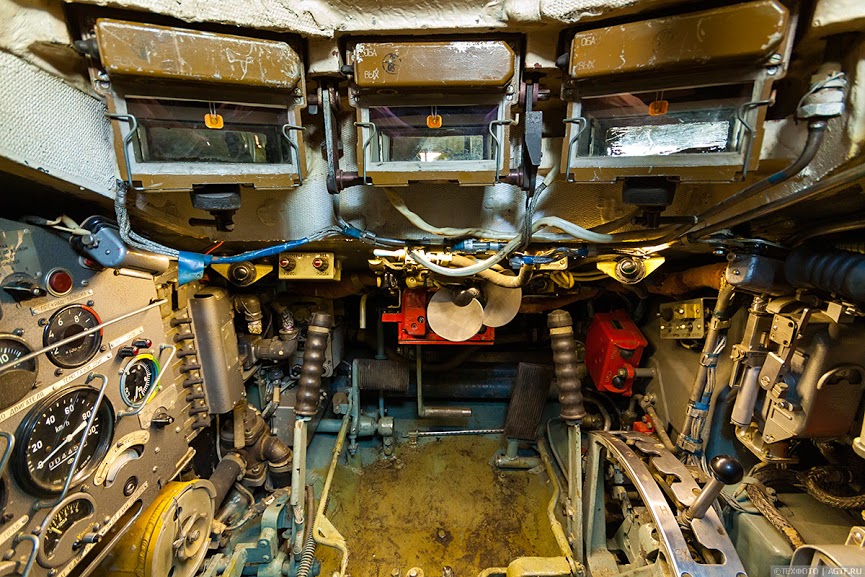
The left side of the cabin is dominated by the instrument panel. Just behind it is the front left hull fuel cell, and behind that is a stack of accumulator batteries.
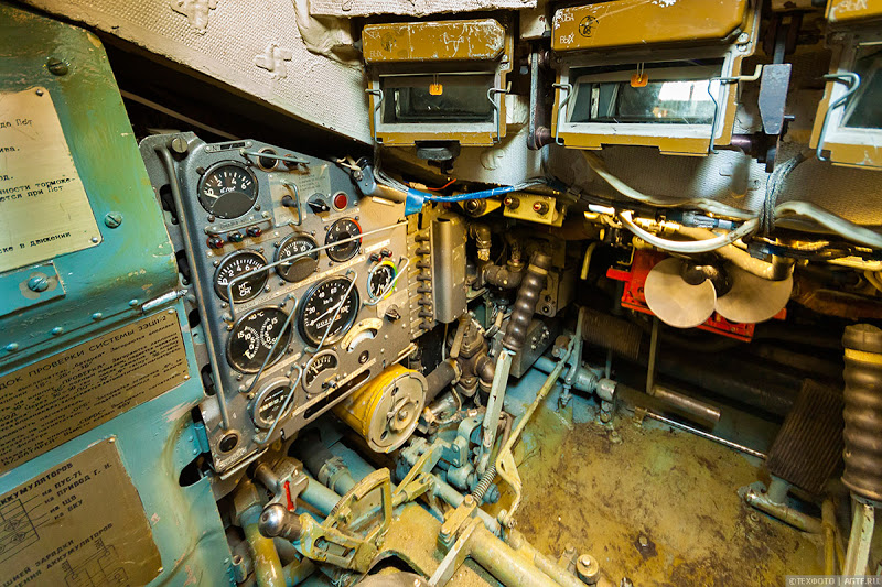
And on the right side of the driver's cabin, there's the hatch opening and closing mechanism, and behind it is the GO-27 gamma radiation detection unit system with its control board direction under it. The red boxes at the front of the hull are the fire location and warning indicator box (left) and fire extinguisher activation boxes (right), previously mentioned in the "FIREFIGHTING" section.
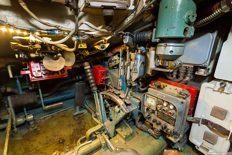
Lighting is provided for by a single dome light affixed to the ceiling of the station, just behind the driver's hatch and behind the driver's head, which is a rather poor idea since most of the light would be blocked by the driver, so finding the buttons on some of the control boards is harder than it should be.
Just like the gunner and commander, the driver gets a small plastic fan right under his nose to help cool him down.
The driver is furnished with a GPK-59 gyrocompasss. It is particularly useful when driving underwater since there's no scenery to refer to. To use it underwater, the driver memorizes the figure indicated on the gyrocompasss dial while on land. This tells him about the orientation of the tank. Once the tank enters water, the driver can refer to how much the dial deflects whenever he steers left and right to know how much and how long he must steer in the opposite direction in order to reorient the tank back towards its original travelling direction.
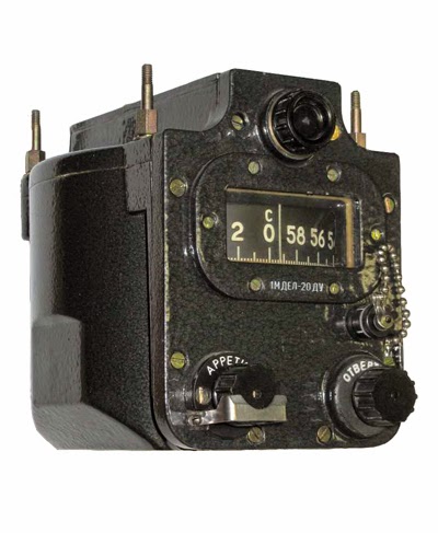
The use of gyrocompasses can perhaps be labeled as a less sophisticated form of an Inertial Navigation System (INS), advanced versions of which are often present in modern combat vehicles due to their independence from outside input contrary to a GPS-based navigation system.
You can see how the GPK-59 works on this video here.
The T-80 is speedy, no doubt about it, but unfortunately, it is not as nimble as it can be. While certainly able to turn fast, it isn't too graceful, and this can be blamed on the rather antiquated lever-type steering system with power assist. Though workable, it's a disappointment compared to German and American tanks that had long transitioned to motorcycle-style handlebars and steering wheel-type configurations.
The driver has a bank of three periscopes for driving visibility, arranged in an arc to give a better panorama of where the tank is going, which, in the T-80's case, is sort of a mix between necessity and luxury. Driving as fast as the T-80 can demands better-than-usual situation awareness on the driver's part as a safety measure, and compared with the earlier T-64 and T-72 with their single wide angle periscope, the T-80's three better facilitates quick maneuvering. There are two variants of the same basic periscope layout; the original version where the periscopes are exposed, and the modified version introduced on the T-80U where a peculiar roof was added on top.


At night, the driver suffers rather like all of his Soviet tankist brethren, only a bit worse. He is supplied with a single TNP IR imaging periscope. It facilitates a viewing distance of no less than 30 m, within which anybody is guaranteed to be able to discern terrain features and obstacles, but because only the center periscope can be swapped out, the driver's field of view is rather narrow compared to the TNPO-160V used in the T-64 and T-72, which has a much wider aperture. With a view distance of only 30 meters and a bad case of tunnel vision, all the merits of the T-80's speed become irrelevant.
The driver is supplied with a face shield. It can be installed just behind the periscope, and it hooks up directly to the tank's electrical system. The face shield is mainly used when driving in convoys, serving to protect the driver's face from the dirt and smoke (and in the T-80's case, hot exhaust plumes) of the leading tank as he drives with his head outside his hatch. It is only used when enemy contact is not a concern, as the shield prevents the cannon from depressing.
TRANSMISSION, SUSPENSION

The radically higher forces following the implementation of a gas turbine engine wore out the T-64's small diameter lightweight roadwheels and suspension at an alarming rate. Hence, the T-80 received an all-new reinforced torsion bar suspension system paired with larger and sturdier forged aluminium roadwheels with a diameter of 640 mm, and because of the much higher rolling speed of the tracks, it became necessary to have five return rollers instead of the usual three in order to provide more dynamic support, and the RMSh tracks inherited from the T-64 required some modifications as well. Because of the extremely high spinning speed of the roadwheels, even the thick rubber rims were not enough to handle the stress, so the tracks needed to be outfitted with thick internal rubber pads.

The T-80 uses a hydraulically assisted mechanical syncromesh transmission with dual planetary gearboxes and dual final drives. There are four forward gears and one reverse gear. The brakes are of a disk type, hydraulically operated. The T-80 turns on a false pivot, meaning that to turn the tank on the spot, one of the two the tracks are locked in place while the other drives the tank around it. This system of neutral steering is mechanically simple, but vastly inferior to a pivot-type steering system where one of the tracks is run at the desired speed while the other is run slighy slower in the opposite direction. Besides being slower, false pivot steering creates a huge amount of friction and places more strain on the inactive track, leading to a quicker gradual weakening of the track and a slightly shorter lifespan. To counteract this issue, the driver may "wiggle" the tank when turning so that the tension in the inactive track is released.
The transmission uses B-3V synthetic oil, of which 60 liters is needed. The same class of oil is used in helicopters like the Mi-17. If you're interested in this sort of stuff, you can read more about it here.
Because of the front-heaviness and high speed of the tank, nose diving into ditches and ruts would be particularly harsh on both the suspension and the crew. To alleviate the stresses of rough driving, the front two roadwheels and rearmost wheel are outfitted with hydropneumatic shock absorbers borrowed from the T-64. These aided recovery as the tank traversed natural obstacles.


The curb weight of the T-80B is 42 tons, or 42.84 tons in a combat configuration.
T-80U: 46 tons, 46.84 tons.
Stripped of additional armour, the T-80, T-80B and T-80U exert a ground pressure of 0.83 kg/sq.cm, 0.864 kg/sq.cm and 0.93 kg/sq.cm respectively.
ENGINE
The T-80 uses the GTD series of engines, a family of gas turbine engines. The turbine blades and turboshaft spins at 26,650 rpm, but the gearbox (consisting solely of reducer gears) lowers this figure down to a maximum of 3,554 rpm on the seventh gear.


The two air intakes for the engine are very substantial, which is to be expected, since gas turbine engines are in essence jet engines - turboshaft engines, to be specific, and huge volumes of oxygen is needed to sustain combustion.


In the photos above, you can see the engine deck and the engine itself along with the air intake grilles and the two ducts behind the engine that lead up to them. It is well known that the biggest nemesis to any jet engine is the ingestion of foreign objects. The cyclone-type air cleaners built into the rear of the engine shoulder most of the burden of filtration, but since it can only ensure air purity of 98.5%, the engine will ingest a small portion of pollutants all the same, but contrary to popular belief, the dust consumption tolerance of gas turbine engines . To counteract the buildup of gunk on the turbine blades, the designers implemented an ingenious solution involving vibration whereby the turbines would be shaken by high frequency vibrations produced by a system of motorized hammers. The hammers were tuned to vibrate the turbine blades at resonant frequencies, causing them to shake off any "pollutants" gunk-ing them up, which are blown out by blasts of compressed air. This purging process occurs during the startup procedure, and during the deactivation procedure. This system is not dissimilar to ultrasonic polishing for jewellery, and the sum of all of the individual engineering solutions was so effective that in fact, the T-80U surpassed the T-90S in engine during comparative endurance trials in India. The T-80 was a top-A student during initial tests as well, passing its hot climate trials in the Karakum desert in Turkmenistan with flying colours.
A portion of the engine's many essential life support systems can be accessed by simply opening up the engine deck. Scheduled maintenance and regular check-ups can be done from outside, but to do any serious repairs on the engine or any of the drivetrain components, the entire powerpack (the transmission and the engine are integrated into one unit) must be lifted out. Very little dismantling is needed. The whole thing just comes out - if you happen to have a large winch at hand, that is.
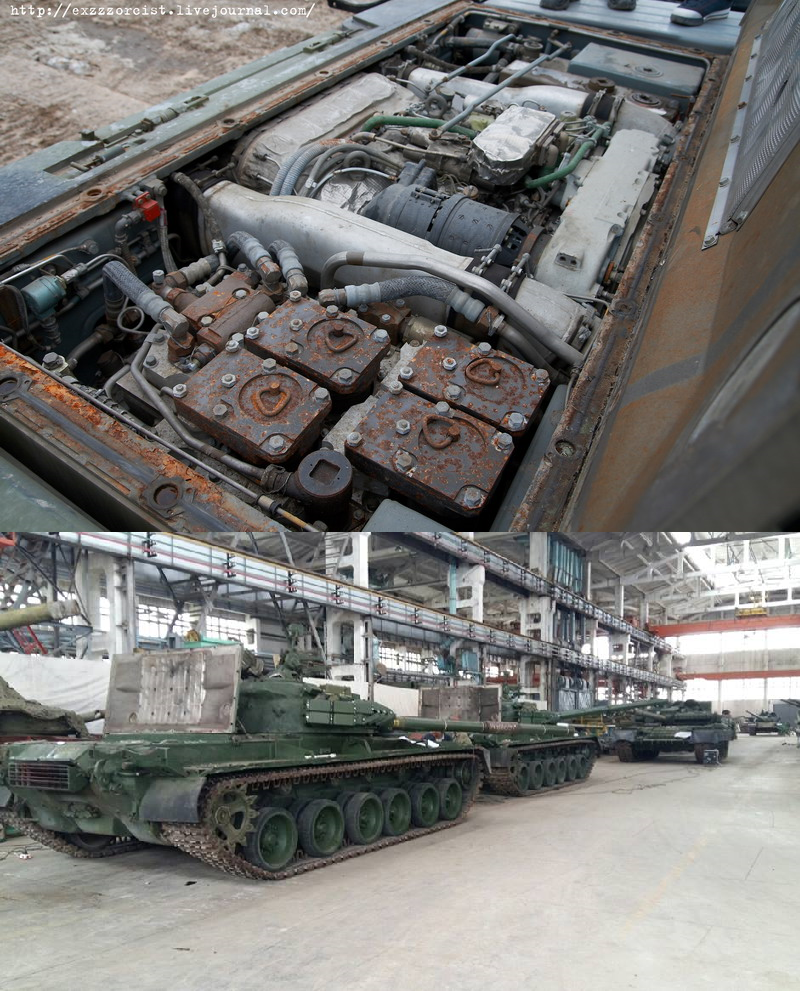
However, the engine deck itself could be considered something of a chink in the tank's armour.
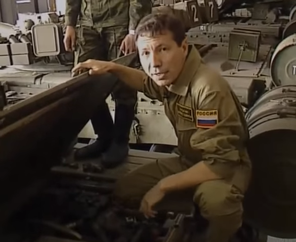
At only around 14mm thick, it isn't really worth much when armour piercing bomblets start raining down from above, although it is still sufficient when faced with low-end autocannon fire. Thankfully for the T-80, the majority of sky-borne autocannons under the NATO banner are pretty anemic. Among them are the M197 and M230 chainguns firing the 20x102mm and 30x113mm shells respectively, which are so weak that the AP shells would glance off and the HEDP shells will either fail to fuse or detonate at such a steep angle that they will be ineffective. However, due to low structural stiffness from the insufficient thickness and lack of reinforcing ribbing, 30x173mm ammunition - namely the DU type used on the GAU-8 on the A-10 ground attack jet - will possibly tear through the deck even at angles of attack of around 20 to 30 degrees and potentially start fires, rupture important cabling or compromise some important subsystem related to the normal functions of the engine. That is assuming that the A-10 dives at a steep enough angle, of course. Fortunately for all Soviet tanks, A-10 pilots are trained to attack at very shallow dives in the vicinity of 3°. At that sort of angle, there is practically no chance of achieving any meaningful hits on the engine deck, let alone perforating it.
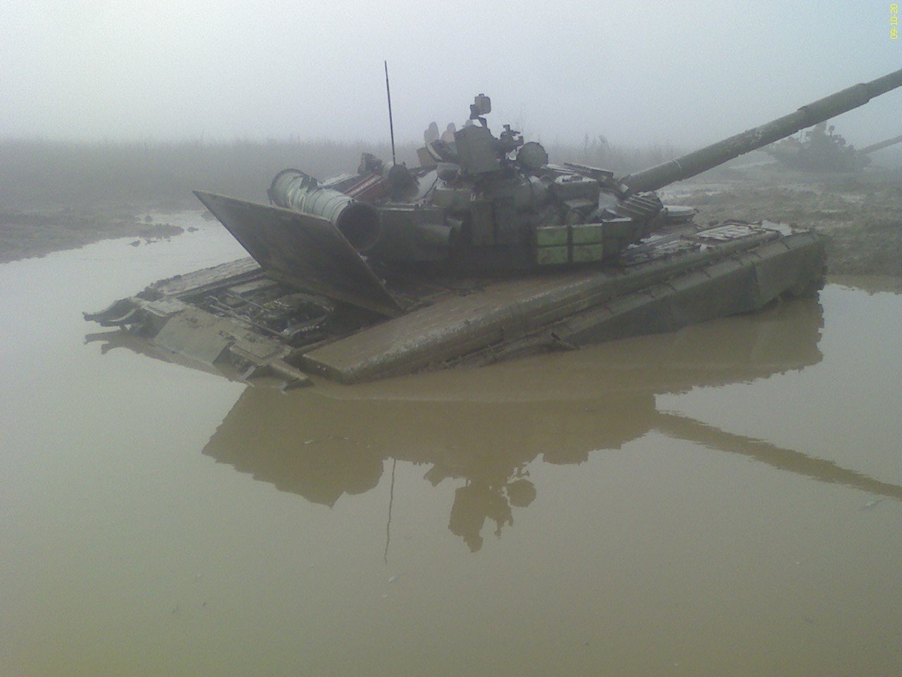
IF the tank was attacked with autocannon fire from a steep dive, then it is some consolation that the T-80's biggest nemesis the Abrams has a similar problem.
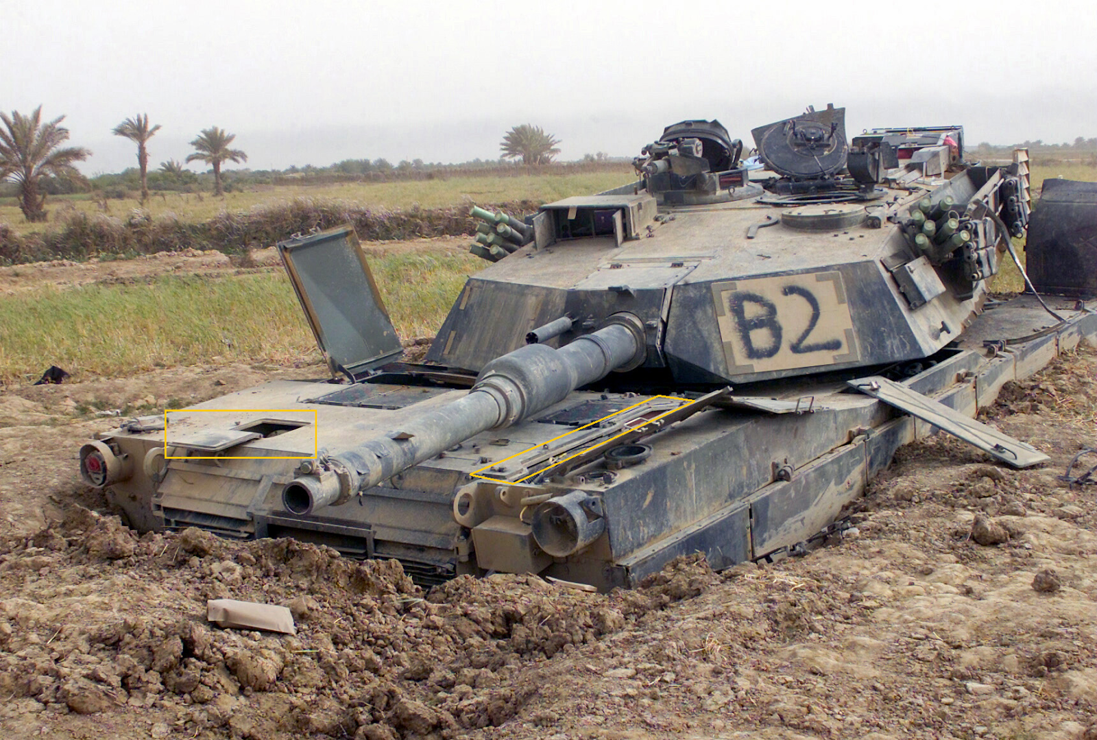
But really, there's no use denying that gas turbine engines have had more than their share of controversy, and for the most part, the controversy is not far off the mark. The most sanguine of any gas turbine engine's properties is of course the prodigiously high acceleration potential thanks to high torque output at low revs, but the price for such performance is steep.From a defensive standpoint, the act of simply sitting idle to ambush or in wait of attack drains the tank's fuel reserves as prodigiously as when the tank is on the move, and if the tank were to be involved in a breakthrough assault as it was designed to do, the same issue prevents it from exploiting a successful breach and penetrating deep behind enemy lines.
Aside from that, one will find no small number of online sources repeating the claim that compact dimensions and low mass compared to conventional diesel powerplants are main selling points of this type of engine. The GTD series for the T-80 are no lighter than most diesel tank engines at a hefty 1050 kg (dry), and little smaller, measuring in at 1.494 x 1.042 x 0.888 m (L-W-H), compared to 1.480 x 0.896 x 0.902 m for the V-46 diesel V-12 engine.
An advantage to the use of jet fuels is that it will not gel up unless the ambient temperature is Arctic low, unlike raw diesel which will in fact gain viscosity in deep sub-zero temperatures if not mixed with some sort of antifreeze. The engines themselves can operate in ambient temperatures of down to -40°C and up to +40°C, but the true heat limit is significantly higher at +55°C, though running the engine at those sorts of conditions entails an extreme reduction of power. In addition to that, the GTD series of engines take no more than just 3 minutes to start up at temperatures of -40°C. That is more than 10 times shorter than the time it takes for a T-72 to get moving. This gives the T-80 a huge advantage in response time, which means that reinforcements can arrive around 40 minutes sooner, but the price of this blessing was very, very steep indeed. The price of the GTD-1000T was 10 times higher.
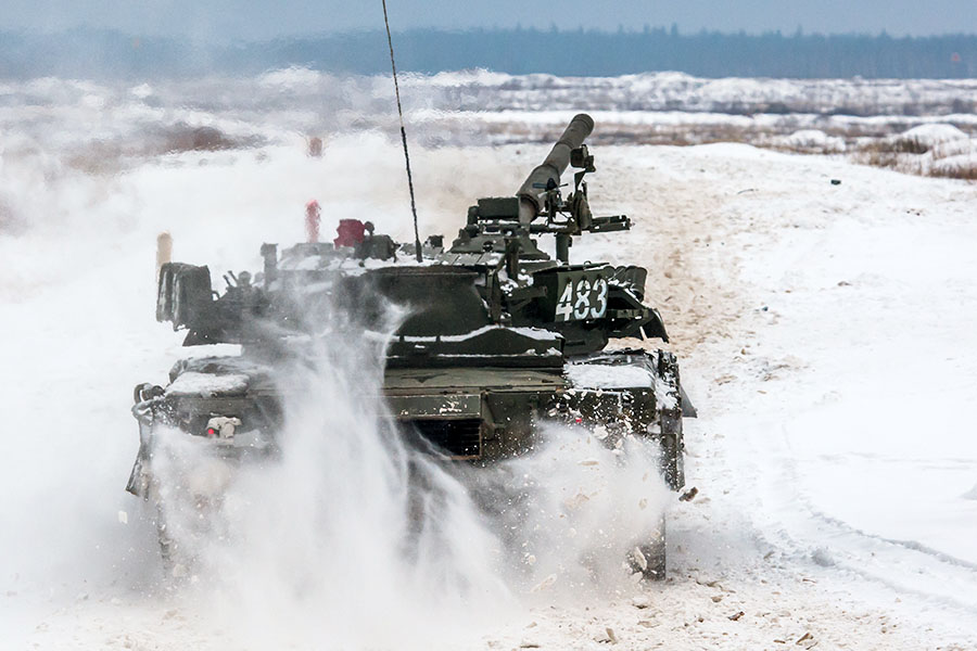
GTD-1000T
To the layman, the lower power output would ostensibly mean that the T-80 is less agile than something like the M1A1 Abrams, but it must be remembered that the T-80 was nearly 36% lighter.
Power - 1000 hp (745 kW)
Torque -
RPM - 3554
GTD-1000TF
The newer GTD-1000TF for the advanced T-80B introduced in 1978 brought small but essential incremental improvements in both power output and fuel economy, which were achieved with the addition of a supercharger. Now, the engine is capable of developing 1100 hp, thanks to more oxygen fueling its fire, and the specific fuel consumption rate at full power was decreased slightly from 240 g/hph of the GTD-1000T to 235 g/hph (319 g/kWh).
Though the M1 Abrams technically had a superior power to weight ratio to the T-80B, it was a negligible difference.
GTD-1250
To compensate for the added weight of Kontakt-5 armour on the new T-80U, it was necessary to take another step forward and increase the power of the engine yet again, but this was not done until 1990. As its name suggests, the GTD-1250 can put out 1250 hp. The fuel efficiency of the GTD line-up reached its peak so far at 225 g/hph (306 g/hph).
Though still less economic from a design standpoint, the actual fuel consumption rate was nevertheless lower and the new engine gave the T-80U a small, but practically negligible edge in agility over the M1A1 and its descendants.

The GTD-1250 uses a modified exhaust port with an interrupted rectangular grille pattern instead of squares like on the GTD-1000T.
Net Power Output: 1250 hp
Max Torque Output: 4395 Nm
Supplementing the engine is the GTA-18 auxiliary power unit (APU). It is a small 30 hp generator outputting 18 kW. Only the command variants are equipped with an APU.
WATER OBSTACLES

For all the sacrifices that needed to be made to gain the extraordinary speed of the turbine engine, the ability to cross rivers was not one of them. The T-80 is provided with a proprietary "Bord" or "Bord-M" snorkel kit, allowing to drive into and across rivers as deep as 5.5 meters, and ford streams down to 1.8 meters deep with some preparation. From a distance, the snorkel configuration is ostensibly similar to the one used on the T-64, but the only real similarity is the implementation of a snorkel-mast where the commander can sit and direct the driver.


Photo Credit (Left): Maxim Volkonovsky
Ventilation for the crew is provided by the snorkel-mast, which is installed by locking it onto the commander's hatch. An internal ladder allows the commander to climb in and out of his station, and if necessary, the entire crew can escape a drowned tank through the snorkel.


Photo Credit: Maxim Volkonovsky
The tank is provided with a snorkel adapter for the engine air intakes. The adapter is a simple, totally hollow shell made with thin sheet steel, encompassing both air intakes and curving to form a pill-shaped inlet duct. It is stowed in a special container mounted at the rear of the turret. Alternatively, it can be left attached to the air intakes for convenience, like in the picture below. In that case, though, the range of traverse of the turret is severely restricted.

The adapter also serves the secondary but equally important function of keeping the air intake grilles from being submerged or splashed with the water blown up by the exhaust. The clip below shows an early T-80 prototype using a pair of what appears to be repurposed commercial ventilation ducts as an interim solution for the water-being-blown-up phenomenon.

While the pressure of the exhaust gasses is enough to eliminate backflow into the exhaust port in shallow water, it is not powerful enough to do so in deep water, making it impossible to use a valved exhaust cover like on the T-55, T-62 and T-72 for deep water driving. Instead, an exhaust tube is used to vent the exhaust gasses out and above water. Installing the exhaust tube requires the repositioning of the regular rectangular exhaust port, which can be hinged up and locked in place, as you can see in the photo below.
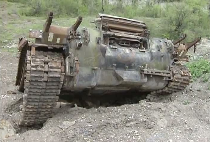
The exhaust port adapter is stowed away in a metal bin mounted on the rear of the turret.
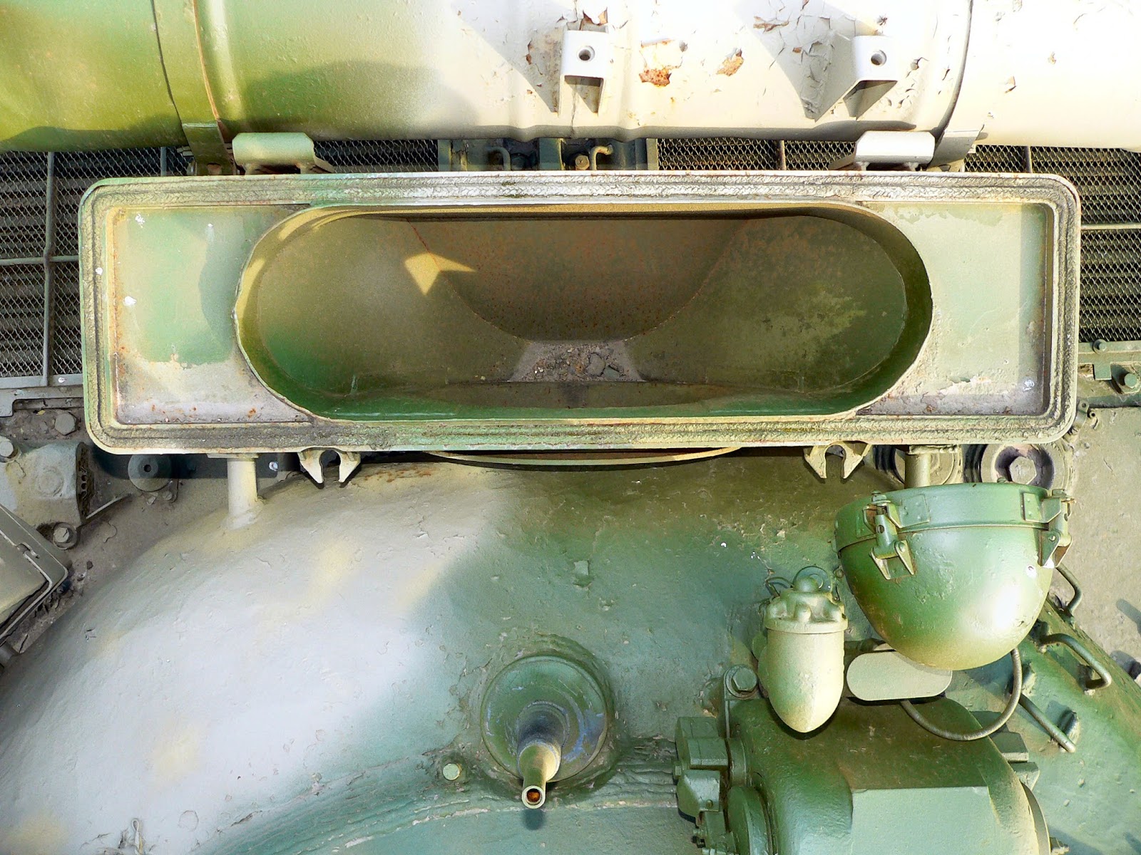
Crew members are each given a closed-circuit IP-5 rebreather for emergency use. It comprises a watertight, form fitting gas mask, a chemical respirator chamber containing potassium superoxide (KO2), and a flotation collar. The rebreather uses the chemical reaction between potassium superoxide and carbon dioxide, activated by water from the user's breath reduce the former two to oxygen and potassium carbonate. The freshly produced oxygen gas is mixed into the previously exhaled breath to replenish its oxygen concentration for rebreathing. The crew usually puts the IP-5 on before entering water as a precautionary measure.
 |
| IP-5 |
ROAD ENDURANCE
In terms of fuel efficiency, the GTD-1000T was ostensibly unremarkable, guzzling jet fuel at the incredible rate of 240 g/hph (326 g/kWh), while its American cousin the AGT-1500 had a specific fuel consumption of just 213 g/hph (290 g/kWh) while simultaneously offering higher power. To the layman, this might be mistaken as clear proof of the technological inferiority of the GTD engines if this was taken at face value, but the layman forgets to take the "hp" in g/hph into account. Multiplying 1000 hp with 240 g/hph yields 240,000 grams per hour, which translates to 192 liters of TS-1 per hour at full power. In real number terms, this is lower than the consumption rate of the AGT-1500 by 25%.
For an engine of about the same size and weight, this is perfectly reasonable performance. However, it is always necessary to strike a balance between striking speed and striking distance, and while the raw performance of the GTD-1000T may not be as optimal as desired, its dimensions and foundations enabled it to be easily uprated whenever the need arises. The best example of this is the GTD-1250, having a much higher power output of 1250 hp, while at the same time offering lower specific fuel consumption rates of 225 g/hph. In neal number terms of efficiency, the GTD-1250 gave more power for every liter it took by 6.9% than the GTD-1000T, while the GTD-1000TF offered 2.3% better efficiency.
However, all of that is academic. Actual mileage testing has yielded some very interesting tangible results for the GTD-1000T engine. The engine consumes between 430 liters to 500 liters of standard TS-1 jet fuel for every 100 kilometers (62 miles) traveled on paved roads, or 450 liters to 790 liters for the same distance but on dirt roads, depending on the severity of the terrain. Assuming that the tank does not stop even once during its journey, the T-80 can travel between 233 kilometers to 409 kilometers on a full tank of fuel when driving cross country. Comparative testing of the T-80U against the Leopard 2A5 showed that while the piston-engined Leopard 2A5 could cruise around on gravelly mountain roads for a distance of 370 km, the T-80U could achieve practically the same result at 350 km. This is fine if both tanks were used for the same purpose, but the Leopard 2 was designed to defend Europe, while the T-80 was designed to invade it.
DISTRIBUTION
The best tank in the Soviet Union was also arguably the best tank in the world for a good long while. This, however, had the unfortunate side effect of ballooning the cost of each T-80 to up to three times as much as its cousins, but most importantly, a single T-80 cost nearly as much as an M60A3! What a nightmare.
Because of this predicament... uhhh...

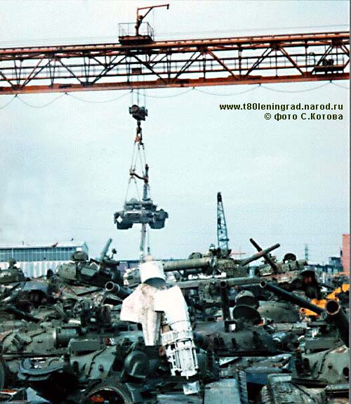
REFERENCES
http://klimov.ru/en/production/landmarine/GTD-1250/
http://morozovkmdb.com/eng/body/t80ud.php?page=history5
http://perfectumlab.com/gallery/panorams/tours/military/t80bv/?h=377.79&v=10.98&f=155.00&l=gunner&m=view_fisheye
http://militaryforces.ru/weapon-3-60-375.html
http://www.kotsch88.de/f_agava-2.htm
http://www.romz.ru/print.php?module=catalog&lang=ru&furl=kompleks-pnk-4s-01-s-pricelom-tkn-4s-01
http://www.romz.ru/ru/catalog/kompleks-pnk-4s-01-s-pricelom-tkn-4s-01.htm
http://lzos.ru/en/index.php?option=com_content&task=view&id=71
http://lzos.ru/en/index.php?option=com_content&task=view&id=30&Itemid=44
http://www.milge.net/index.php?mid=data&document_srl=4132&order_type=asc&sort_index=title
http://htka.hu/kozosseg/discussion/42276/t-80
https://www.maxwolf.ru/armor/fording_e.html
http://armor.kiev.ua/wiki/index.php?title=%D0%A2-80%D0%A3_%D0%B2_%D0%A8%D0%B2%D0%B5%D1%86%D0%B8%D0%B8
http://maxwolf.livejournal.com/67553.html
http://army.lv/?s=744&id=0&c=0&p=19
http://all-tanks.ru/content/osnovnoi-tank-t-80
http://ru-armor.livejournal.com/63588.html
http://btvt.narod.ru/5/80inside/80inside.htm
http://www.zavod9.com/en/?pid=18
http://feodosya.all.biz/prozhektor-l-4-l-4a-so-stabilizatorom-toka-st-17-5-g289541#.VtFxXX2GPIU
Wonderful article, as usual :)
ReplyDeleteA few corrections if you dont mind:
1, On the turret roof of the T-80B, it isnt a ventilator. It is the crosswind sensor for 1A33 FCS.
2, Commander's cupola: On the earlier variants, it is totally unbalanced by the AAMG mounting, making it very hard to use. (unlike T-64, which had electric drive, and the T-72, which had a separte ring for the AAMG.) One solution was welding some racks that held a few track links to balance the cupola.
3, 1G42 and 1G46 were amongst the best FCS of their time, granting much higher accuracy than the 1A40. Yes there was some problem with sight and stabilizer gyro misalignment, but this occured if the tank wasnt maintained properly.
4, turret roatation mechanism was hydraulic, not electric. Also, its fire hazard was negliglible, due to low amount of hydraulic fluid.
5, transmission: T-80, T-80B, and also probably T-80U had 4 speed lateral gearboxes. As far as I know only T-80UD used 7 speed.
6, T-80U never used remotely controlled MG. That was the T-80UD. On T-80U, there aere 3 points on the turret, around the cupola, where the commander can fix the MG mounting. A very poor solution.
Thank you for the corrections! I read this comment very soon after posting, but unfortunately, I could not do any more edits, as my laptop broke down just a few days before posting. I used my phone to post instead, but updating the articles with it is almost impossible because of how large the article file is. It is making Chrome crash :(
Delete1. I had come across a diagram from a manual that shows the "ventilator", but I forgot about it and could not correct it before I posted.
2. I am not aware of these tracks. I will have to look closer at some photos! However, this is not corroborated by the fact that when the cupola spins, the machine gun spins as well.
3. Well, certainly, if compared to previous Soviet models, but what about foreign analogues? In that respect, 1G42 and 1G46 are either negligibly better or no better at all, in my opinion.
4. 2E42 series had hydraulic vertical drive and electric horizontal drive. Amplidyne generator is visible in one of the photos presented in the article.
5. Ah, I see. Thank you for the heads up.
6. Hmm.. are you sure? Maybe it is hard to differentiate between U and UD from the front, but I could swear that I have seen T-80U with remote machine gun before...
For point 2:
Deletehttp://s12.postimg.org/6xh1yey3x/t804nh.jpg
Also, read more here: http://www.kotsch88.de/f_t-80_fla.htm
3: FCS was quite good. Somewhat inferior to Abrams or Leopard-2 (for 1980s variants!) but far superior to anything other in the world, including Challenger-1. T-80 can fire quite accurately out to 2000m, but after that, accuracy drops rapidly.
There is a report of testing in greece, but unfortunately, a horrible translation, some parts barely understandable. Some of the T-80's firing results were excellent, but in other tests, quite mediocre. There were two main problems: 1, FCS wasnt adjusted properly. Some results improved singificantly after readjusting. 2, They used 3P31 training ammo, which became inaccurate beyond 1500m. However, the problems with hitting targets above 2000m is definitely one of the shortcomings of the FCS. http://www.steelbeasts.com/sbforums/showthread.php?t=20551
4: Yes, you were completely right, it was my mistake.
6: Absolutely sure. T-80U was never built with remote controlled MG. However, there is a rare variant that indeed looks like an U, but in fact a mix of BV and UD: the T-80UE-1, which was produced from BV hulls and UD turrets. Only this has the remote MG besides the UD and the 0-serie T-80A.
wow!!!!!!!!!!!
ReplyDeleteWhere is part about active and pasive protection system? They were integral for all late T-80s.
ReplyDeleteWell, I have already mentioned the smokescreen generating systems. There's nothing more to talk about, I don't think. Shtora was only installed on very late variants, and there are so few of them that they are militarily irrelevant.
DeleteCorrection of the correction: Turret traverse drive is indeed electric in 2E42 system.
ReplyDeleteWhat is T-80U's armor composite and how much equivalent RHAe protection does it have?
ReplyDeleteHow is the protection of the T80U in comparison to the T-72B in late 1980s?
Around 550mm vs KE, and 620mm vs HEAT, without Kontakt-5. It is very similar to T-72B, except that the T-72 has poor ERA coverage, (only 45-55% frontally) with huge unprotected gaps on turret.
DeleteI have no idea, and I highly doubt that information on the composition of the T-80U's turret is available in the public domain. I haven't yet come across any convincing proofs yet, which is why I am leaving that section mostly blank for now. However, the consensus is that it is weaker than the turret of the T-72B, and I am leaning in favour of this assessment. While the ceramic packages used by the T-64 family (including the T-80) are expensive, NERA arrays appear to be more effective still, and are cheaper to boot. However, without tangible evidence to prove so, I will not be making any conclusions.
DeleteFortunately there is available information by polish expert, Jaroslaw Wolski (militarysta):
Deletehttp://defenceforumindia.com/forum/threads/mbt-armour-active-and-passive-cross-sections-and-descriptions.64233/
WOW!
ReplyDeleteAwesome picture cavalcade.
thanks for this.
My pleasure!
DeleteThis comment has been removed by a blog administrator.
ReplyDeleteI'll see what I can do to get it up by next month.
DeleteThis comment has been removed by a blog administrator.
ReplyDeleteHi! Thank you so much for writting down this article: I've been waiting for it for so long.
ReplyDeleteHowever, I wish there was some info on the T-80's latest variant: The T-80 UE-1, already mentioned in the comments above. This one paired not only the UD turret with an U chassis, but also adss a more than welcome and needed upgrade in the form of the "PLISSA" sight, wich is essentialy an analogue for the T-90s " ESSA" and makes use of french thermal vission technology in the form of the Catherine NT\XP series.
I don't know how many of these are in service but I'm aware a contract for at least 214 upgrades were made back in the early 2010s, with estimations ranging from 200 to 500 in service -althought the later figure seems an overstimation to me.
In any way, it's clear the 2nd Mech Div and 4th Tank Div - AFAIK russian main users of the T-80- still had a number of older T-80Us or even BVs in service in 2015, by pictured published by the Russian MODF. But info is contradictory to say the less, for T-80 was supossed to be passed out by 2014...
I wonder if you chose to let this newer, french tech-based sights out of the scope of your articles for this not being actual SOVIET technology, for they are almost unmentioned both in this article as in the previous T-72 one - as is common knowledge, T-72B3's "SOSNA-U" also derives from this family. Is that so?
If so, I really hope the upcoming T-90 article does include some info about these systems - at least on the form of the ESSA sight.
A comparison between this systems and western ones would be more than welcome, if possible!
Anyway, hope I've not bothering you with my request and please: Keep up the incredible work you're doing.
Greetings from Argentina.
I heard only about 30 tanks were modernised before the funding was shifted to the T-72 upgrades. Also, the tanks were built on modernised T-80BV hulls with turrets taken from T-80UD (which were scrapped because the engine is produced in Ukraine). I also think the 1A45 got some modifications (some of which were made because of the instalation of the thermal sight).
DeleteLooking at FSA videos engaging T-90As with TOWs. Only one successful hit and the T-90 shrugged it off. The others had their SHtoras on and didn't get hit.
ReplyDeleteI've found pictures from the PKN-4 http://forums.eagle.ru/showpost.php?p=2174953&postcount=176 (TKN-4s & PZU-7)
ReplyDelete